[QEC教程]
For the full tutorial, see 範例:QEC 上的低程式碼數位輸入/輸出.
Digital Output/Input
With the 86EVA and ArduBlock, using the external LEDs are blinked by the Digital Output, and the status of the LEDs is received through the Digital Input and printed out through the Serial Port.
硬體說明
- QEC-M-01
- QEC-R11DF0: EtherCAT 16數位輸入通道從站模組
- QEC-R11D0F: EtherCAT 16數位輸出通道從站模組
- 其他: 24V LED
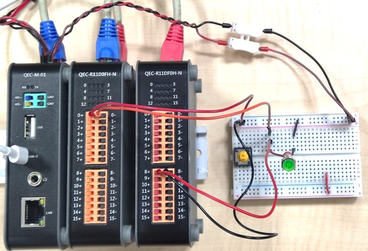
Circuit
請先將QEC-M上的EtherCAT Out網路與QEC-R11D0F的EtherCAT In網路連接,以及QEC-R11D0F的EtherCAT Out網路與QEC-R11DF0的EtherCAT In網路連接。
此範例將使用Vp電源作為QEC-R11D0F Pin0的電源,透過使用QEC-R11DF0的Pin8 作為接收信號腳位。
- Vp電源連接到QEC-R11D0F Pin0+
- QEC-R11D0F Pin0-連到LED的VCC
- LED GND接到QEC-R11DF0的Pin8+
- QEC-R11DF0的Pin8-接回Vp電源的GND
如圖所示。
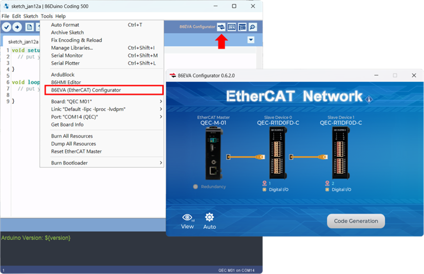
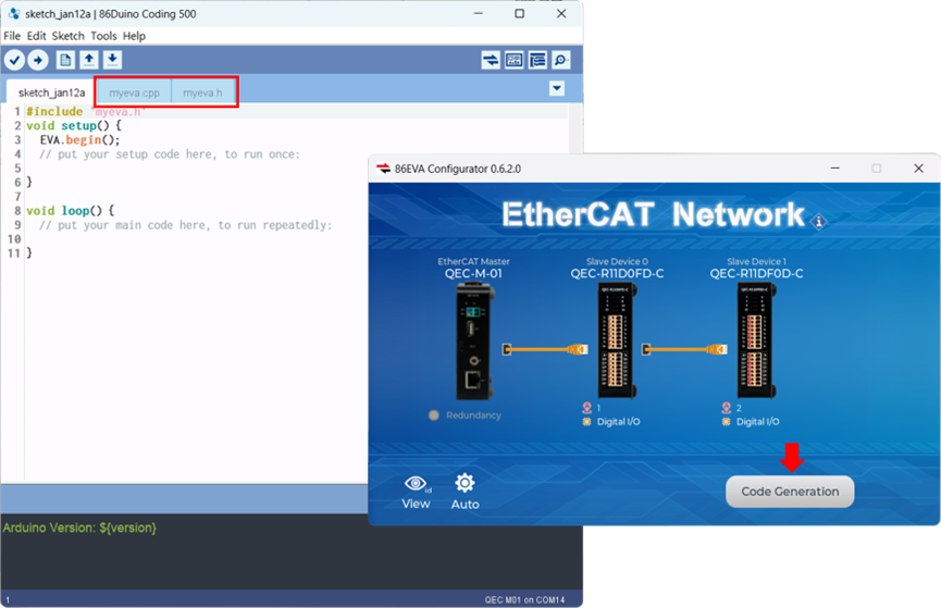
Step 1: 86EVA, EtherCAT Configuration
Go to the 86Duino Coding IDE, open the 86EVA tool, and configure EtherCAT.
Step 2: Set up the Virtual Arduino Pin and generate the code
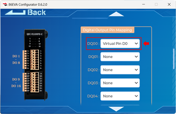
In the screen of the Digital Output slave device, QECR11D0FS, set DQ00 to the Virtual Pin D0 of the Arduino.
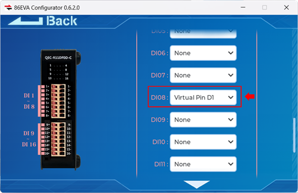
In the screen of the Digital Input slave device, QECR11DF0D, set DI08 to the Virtual Pin D1 of the Arduino.
After completion, the 86EVA code can be generated.
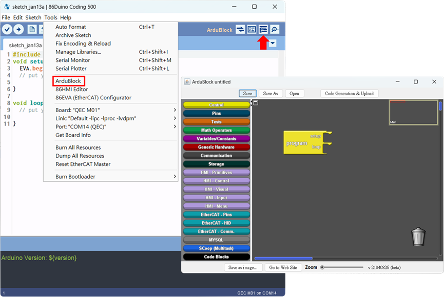
Step 3: ArduBlock setup
Open ArduBlock.
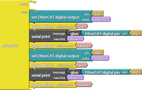
We need to set Output’s Pin0 to High and read Input’s Pin8, then print it in Serial Port, with a delay of 4000 ms. After that, set Output’s Pin0 to Low and read Input’s Pin8, then print it in Serial Port, with a delay of 1000 ms.
The building blocks are as follows.
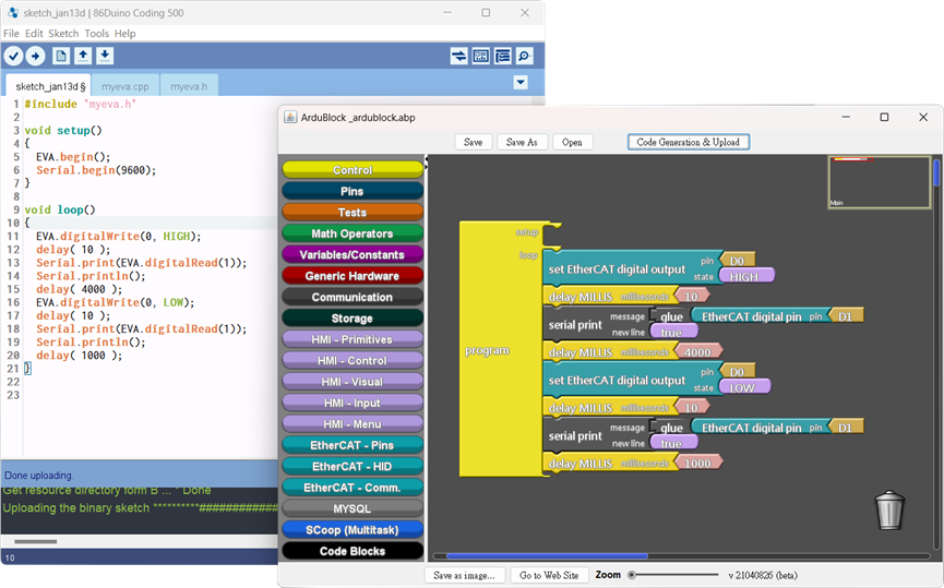
Generate the code and upload it.
學習更多
你可以在下方找到更多關於QEC基礎應用的信息 EtherCAT應用.
You can also explore 程式語法參考 or 函式庫參考 for a more detailed collection of 86Duino IDE programming.