[Visualization widgets]
Object Functions
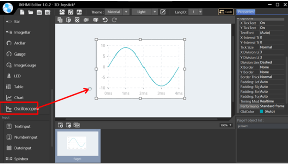
Oscilloscope object.
This object is an advanced function that can present values as waveform changes depending on the measurement input source. It can be used as an oscilloscope function or an input source that must immediately present the value change.
Oscilloscope Properties.
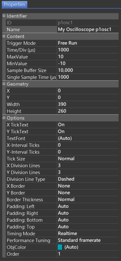
Identifier:
- ID: Unique number that identifies the object.
- Name: User-definable name for the object. It can be used with 86HMI API.
Content:
- Trigger Mode: Oscilloscope draws waveforms mode.
- Free Run: Regardless of the measurement value, the screen is constantly updated at every moment.
- Positive Slope: Upper edge trigger. Updated when the measured value reaches the Trigger Level and has a positive slope.
- Negative Slope: Lower edge trigger. Updated when the measured value reaches the Trigger Level and has a negative slope.
Additional Information:
Positive Slope and Negative Slope modes are mainly used to display periodic high-frequency signals (such as measuring high-frequency square waves of communication signals, etc.). Free Run mode can demonstrate the value currently measured by the sensor.
- Time/Div (μs): Time division in one interval on the X-axis. Unit for μs.
- MaxValue: Maximum value of vertical axis.
- MinValue: Minimum value of vertical axis.
- Sample Buffer Size: Set the sample size to record to buffer.
- Single Sample Time (μs): Sample buffer interval time of sampling points. Unit for μs.
Geometry:
- X: Object X coordinate.
- Y: Object Y coordinate.
- Width: Object width.
- Height: Object height.
Options:
- X TickText: Set whether to display the main tick text of the X-axis (the X-axis is the time unit).
- Y TickText: Set whether to display the main tick text of the Y-axis (the Y-axis is the time unit).
- TextFont: Choose from 6 default font styles. For font configuration instructions, please refer to Theme Management.
- X-Interval Ticks: X interval tick.
- Y-Interval Ticks: Y interval tick.
- Tick Size: Tick size, with options as None, Normal, and Large.
- X Division: X grid number.
- Y Division: Y grid number.
- Division Line Type: Division Line Type, with options as None (no grid), Solid (solid line), and Dashed (dashed line).
- X Border: X border.
- Y Border: Y border.
- Border Thickness: Border thickness.
- Padding: Left/Right/Bottom/Top: Oscilloscope’s padding size of object and border (Left/Right/Bottom/Upper).
- Timing Mode: Mode for calculating time.
- Realtime: Timely mode. It is the general mode of use for oscilloscopes, which can display the original signal more accurately when measuring external signals and is mostly used to measure the actual signal.
- Manual: Manual mode can display self-generated waveforms, such as generating a string waveform with a program and drawing it out.
- Performance Tuning: Set the smoothness of the Oscilloscope in operation.
- Lowest framerate
- Low framerate
- Standard framerate
- High framerate
- High precision
Additional Information:
The Oscilloscope window is too large, and you may need to select a lower Performance Tuning; the Oscilloscope window is small, and you can select a higher Performance Tuning.
- ObjColor: Choose from 4 themed colors. For font configuration instructions, please refer to Theme Management.
- Order: Object order. It can adjust the object order by up/down, which can be viewed on the Object List.
API Functions
addOscSample()
Description
Add Oscilloscope Sample value.
Syntax
void addOscSample(lv_obj_t* id, double value);
void addOscSample(char* name, double value);
void addOscSample(Oscilloscope* id, double value);
Parameters
[in] id
Object ID.[in] name
Object Name.[in] value
Oscilloscope Sample value.
Return
None.
Example
#include "myhmi.h"

double oscData[4] = {100, 75, 50, 0};

void setup() {
  Hmi.begin();
  // ...
}

void loop() {
  // ...
  for (int i = 0; i < 4; i++) {
    Hmi.addOscSample(p1osc1, oscData[i]);
  }
  delay(10);
}
setOscTriggerMode()
Description
Set Oscilloscope Trigger Mode.
Syntax
void setOscTriggerMode(lv_obj_t* id, OSC_TRIGGER_MODE mode);
void setOscTriggerMode(char* name, OSC_TRIGGER_MODE mode);
void setOscTriggerMode(Oscilloscope* id, OSC_TRIGGER_MODE mode);
Parameters
[in] id
Object ID.[in] name
Object Name.[in] mode
Oscilloscope Trigger mode. Options with OSC_POSITIVE_SLOPE/OSC_NEGATIVE_SLOPE/OSC_FREE_RUN.
Return
None.
Example
#include "myhmi.h"

void setup() {
  Hmi.begin();
  // ...
  Hmi.setOscTriggerMode(p1osc1, OSC_POSITIVE_SLOPE);
}

void loop() {
  // ...
}
setOscTriggerLevel()
Description
Set Oscilloscope Trigger Level.
Syntax
void setOscTriggerLevel(lv_obj_t* id, double value);
void setOscTriggerLevel(char* name, double value);
void setOscTriggerLevel(Oscilloscope* id, double value);
Parameters
[in] id
Object ID.[in] name
Object Name.[in] value
Oscilloscope Trigger level.
Return
None.
Example
#include "myhmi.h"

void setup() {
  Hmi.begin();
  // ...
  Hmi.setOscTriggerLevel(p1osc1, 0.0);
}

void loop() {
  // ...
}
setOscTriggerOffset()
Description
Set Oscilloscope Trigger Offset.
Syntax
void setOscTriggerOffset(lv_obj_t* id, long value);
void setOscTriggerOffset(char* name, long value);
void setOscTriggerOffset(Oscilloscope* id, long value);
Parameters
[in] id
Object ID.[in] name
Object Name.[in] value
Oscilloscope Trigger offset.
Return
None.
Example
#include "myhmi.h"

void setup() {
  Hmi.begin();
  // ...
  Hmi.setOscTriggerOffset(p1osc1, 0);
}

void loop() {
  // ...
}
setOscTimeDiv()
Description
Set Oscilloscope X-axis represents the time represented by an interval.
Syntax
void setOscTimeDiv(lv_obj_t* id, int value);
void setOscTimeDiv(char* name, int value);
void setOscTimeDiv(Oscilloscope* id, int value);
Parameters
[in] id
Object ID.[in] name
Object Name.[in] value
Oscilloscope’s X-axis represents the time represented by an interval.
Return
None.
Example
#include "myhmi.h"

void setup() {
  Hmi.begin();
  // ...
  Hmi.setOscTimeDiv(p1osc1, 100);
}

void loop() {
  // ...
}
setOscYRange()
Description
Set Oscilloscope Y-axis Range.
Syntax
void setOscYRange(lv_obj_t* id, double min, double max);
void setOscYRange(char* name, double min, double max);
void setOscYRange(Oscilloscope* id, double min, double max);
Parameters
[in] id
Object ID.[in] name
Object Name.[in] min
Y-axis minimum value.[in] max
Y-axis maximum value.
Return
None.
Example
#include "myhmi.h"

void setup() {
  Hmi.begin();
  // ...
  Hmi.setOscYRange(p1osc1, -10.0, 10.0);
}

void loop() {
  // ...
}
setOscYDiv()
Description
Set the number of Oscilloscope Y-axis grid lines.
Syntax
void setOscYDiv(lv_obj_t* id, double value);
void setOscYDiv(char* name, double value);
void setOscYDiv(Oscilloscope* id, double value);
Parameters
[in] id
Object ID.[in] name
Object Name.[in] value
The number of Oscilloscope Y-axis grid lines.
Return
None.
Example
#include "myhmi.h"

void setup() {
  Hmi.begin();
  // ...
  Hmi.setOscYRange(p1osc1, -10.0, 10.0);
  Hmi.setOscYDiv(p1osc1, 100);
}

void loop() {
  // ...
}
Please see the 86HMI Editor User Manual for more instructions on 86HMI widgets and API usage.