1. Getting started with the 86Duino
The 86Duino integrated development environment (IDE) software makes it easy to write code and upload it to 86Duino boards. It runs on Windows, Mac OS X, and Linux. The environment is written in Java and based on Arduino IDE, Processing, DJGPP, and other open-source software.
ICOP’s QEC is an Arduino-based (86Duino) EtherCAT solution with a dual-core Vortex86EX2 processor developed by DMP Electronic to achieve hardware and software Real-time requirements.
Note: This tutorial works with the QEC-M products series.
1.1 Goals:
In this tutorial, we will achieve the following:
- Download and install the 86Duino.
- Power on the QEC-M-01.
- Make sure the computer recognizes our board.
- Upload a simple blink example.
1.2 Hardware & Software needed
- 86Duino IDE 500+
- QEC-M-01
- USB to Micro-USB cable
- Power Adapter
2. Let’s get started:
2.1. Step 1: Download the 86Duino IDE
The 86Duino IDE can be downloaded from the official website.
Link: https://www.qec.tw/software/

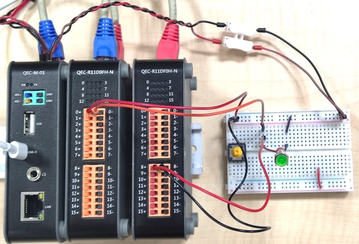
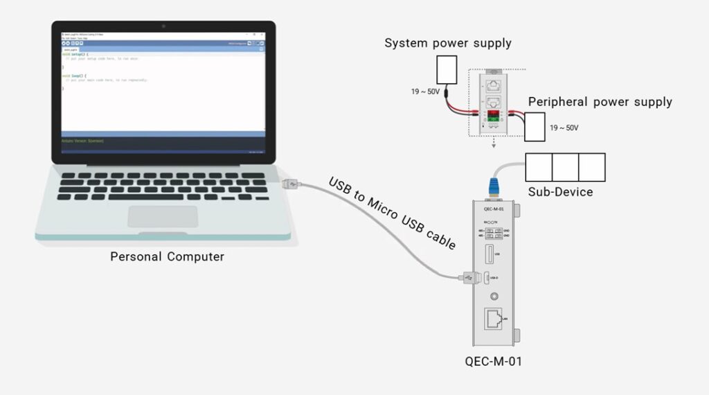
2.2. Step 2: Plugin the power supply for QEC-M-01
There are two groups for the Power Supply in QEC-M-01, Vs and Vp; Both power requirements can range from 19VDC to 50VDC wide Voltages. After powering on, you’ll see the power LED light up.
Note: Vs for the system power; Vp for the peripheral power.
2.3. Step 3: Connect the USB cable

2.4. Step 4: Verify if the device is detected or not
Open Device Manager -> Ports (COM & LPT) in your PC and expand the ports, you should see that the “Prolific PL2303GC USB Serial COM Port (COMx)” is detected, if not you need to install the required drivers.

(For Windows PL2303 driver, you can download here)
2.5. Step 5: Write your first sketch
- Open the 86Duino IDE
- Open the Tools menu from the Menu bar
- Select the correct board: In the IDE’s menu, select Tools> Board > QEC-M-01 (or the QEC MDevice model you use).

- Select Port: In the IDE’s menu, select Tools > Port and select the USB port to connect to the QEC MDevice (in this case, COM9 (QEC)).

2.6. Step 6. Upload your first sketch!
The Arduino development environment has two main parts: setup() and loop(), which correspond to initialization and main programs. Before operating the EtherCAT network, you must configure it once. The process should be from Pre-OP to OP mode in EtherCAT devices.
Once the code is written, click √ on the toolbar to compile, and to confirm that the compilation is complete and error-free, you can click –> to upload.

3. Congratulations
After the power LED on your QEC-M-01 means you have successfully used 86Duino to upload your first sketch into the QEC-M-01!
Stay tuned for more projects on QEC!
Feel free to comment if you have any doubts/queries!
A. Troubleshooting
A-1. Power
Please ensure the power adapter and cords before you plug-in power.
- Power Adapter: 24V/2A
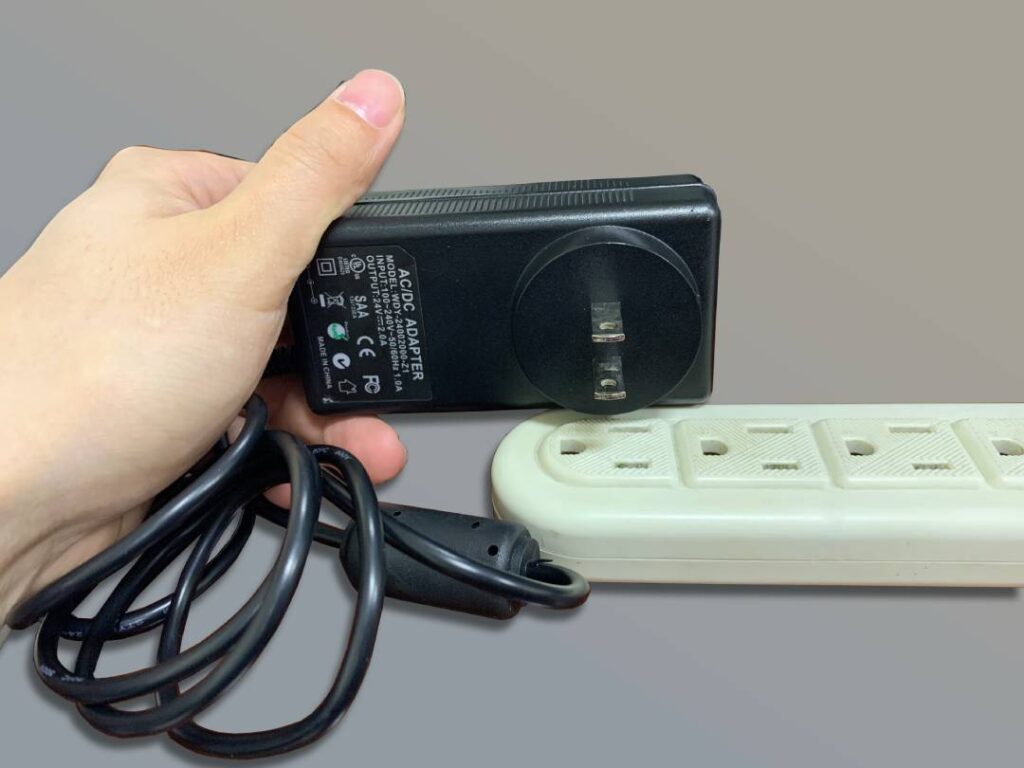
- Power Cord: Red to Red (VCC); Black to Black (GND)
All QEC product series have circuit protection, don’t worry.
The text of the 86Duino reference is a modification of the Arduino reference and is licensed under a Creative Commons Attribution-ShareAlike 3.0 License. Code samples in the reference are released into the public domain.