The QEC ETG.7200 Test Tool is a graphical EtherCAT test application that runs on the QEC platform (86Duino + 86HMI). Plug in any EtherCAT SubDevice, boot the HMI, and you can identify the device, configure PDO mappings, synchronize Distributed Clocks, run a CiA 402 servo drive, and browse the entire object dictionary — all directly from the touchscreen.
It implements the ETG.7200 test specification, so any standard-compliant SubDevice — I/O modules, servo drives, sensors, encoders — work the same way.
Download the User Manual (PDF, English, 3.9 MB) | 中文版 PDF
1. At a glance
- Identify any EtherCAT SubDevice in 30 seconds — Vendor ID, Product Code, supported protocols
- Configure PDO mappings (RxPDO/TxPDO) and verify I/O bidirectionally
- Drive a CiA 402 servo in PP, PV, HM, CSP, CSV, or CST mode — no application code required
2. Six demos, walking through a real bench session
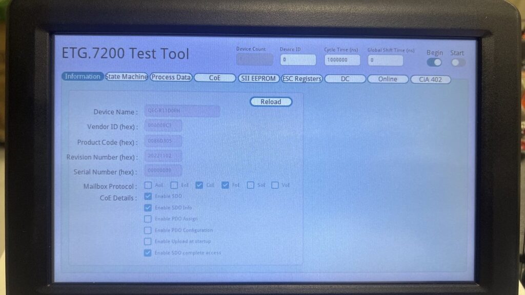
2.1 Demo 1 — Identify any SubDevice in 30 seconds
Toggle Begin ON, switch to the Information tab, and click Reload. The tool calls master.begin() and the SubDevice’s identification is populated automatically. Cross-check Vendor ID and Product Code against the vendor’s ESI file at a glance.
Before/After: empty Information tab with Begin OFF turns into fully populated identification fields after Begin + Reload.
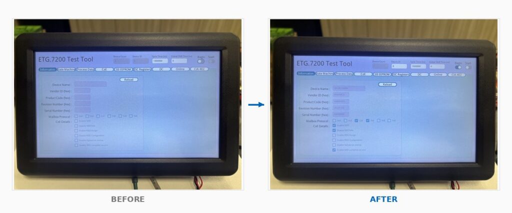
2.2 Demo 2 — Configure PDO and watch I/O light up
On the Process Data tab, pick the RxPDO / TxPDO indices and click Download. sdoDownload() writes the assignment back to the SubDevice. Bring the slave into Op state, switch to the Online tab, and toggle a single output bit — the field LED lights up. Trigger a real input — the bit flips on screen.
Before/After: Process Data tab with empty PDO Assignment becomes filled with 0x1600 RxPDO mapping showing 0x7000 sub-indices.
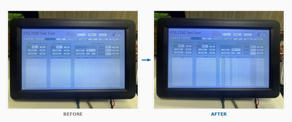
2.3 Demo 3 — Synchronize Distributed Clocks with one button
The DC tab exposes SYNC0 / SYNC1 cycle multipliers and per-slave Shift Time as plain dropdowns. Pick the multiplier, click Set, and setDc() is invoked. Leaving Global Shift Time at 0 lets the master compute a safe shift automatically when you toggle Start.
Before/After: empty DC tab with SYNC0 Cycle Time x 0 becomes Set call successful confirmation dialog.
2.4 Demo 4 — Run a CiA 402 servo in Profile Position mode
Plug in any CiA 402-compliant servo. Enter the axis number, click Attach, and the tool pre-loads the drive’s motion parameters. Pick PP mode, set Profile Velocity / Acceleration / Deceleration, click Enable, type a target position, press Run. The Servo Status panel tracks Position Actual Value to the target with Target Reached lighting up at the end.
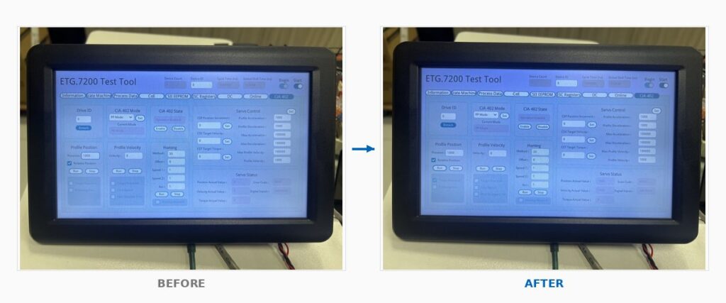
Before/After: Profile Position panel ready with Position=1000 becomes Target Reached checked with Position Actual Value matching target.
2.5 Demo 5 — Drive a servo cyclically with CSP mode
Switch the same drive to CSP (Cyclic Synchronous Position). Type a CSP Position Increment (for example, 1 count per cycle), click Set, and the master pushes a new target position every EtherCAT cycle. Velocity stays rock-steady because DC sync is doing its job. Reverse direction by flipping the sign; stop instantly by setting Increment to 0.
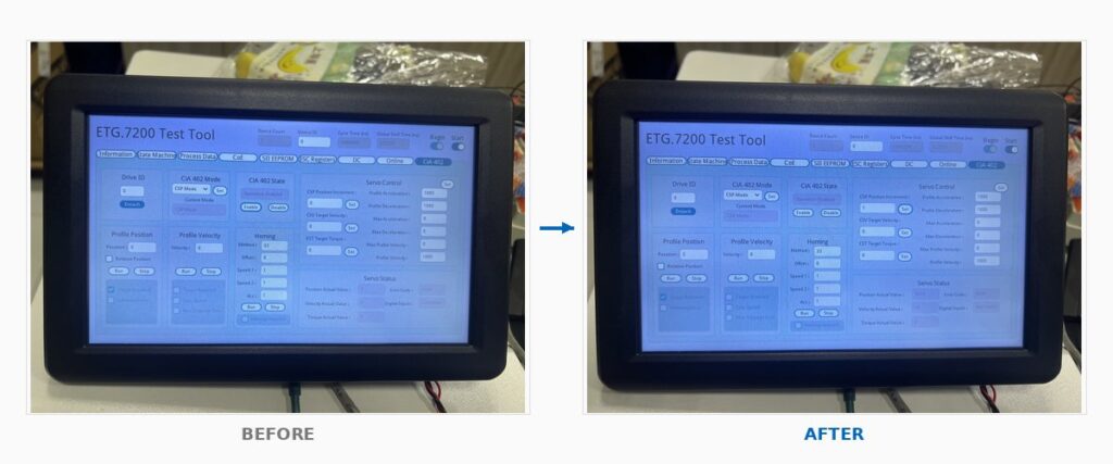
Before/After: CSP mode Operation Enabled with Increment=0 motor still becomes Increment=1 with Position Actual Value accumulating to 3553 and Velocity showing 18.
2.6 Demo 6 — Browse the entire Object Dictionary, write any parameter
On the CoE tab, click OD Generation once. The tool calls getODlist(), getObjectDescription(), and getEntryDescription() to import the SubDevice’s full object dictionary. Click Reload and every entry’s value populates. Pick any object — say 6080h Max Motor Speed — type a new value, click Download, and verify by re-Uploading. Emergency Messages from the SubDevice stream into the bottom table in real time.
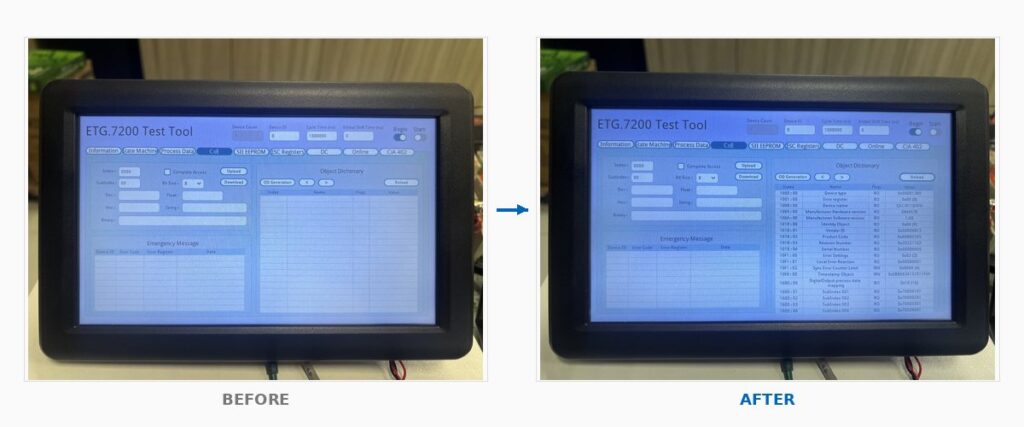
Before/After: empty CoE tab with no Object Dictionary becomes a fully populated table showing all Index/Name/Flags/Value entries from 1000h to 6099h.
3. Why does this save engineering time
- No master-side code required for initial validation. Plug, power, click. You verify the SubDevice works before writing a single line of application code.
- Visual confirmation everywhere. Every operation either succeeds with a confirmation dialog or shows an Emergency Message with a decoded Error Code. No log diving.
- One workflow, any device. The same tool walks you through I/O modules, servos, sensors, encoders — anything compliant with ETG.7200.
- Foundation for production tests. Every operation in the tool maps cleanly to the C/C++ EtherCAT API documented in the manual, so a validated SubDevice transitions seamlessly to production firmware.
4. What’s in the manual
The complete v1.6 user manual is 58 pages covering:
- Chapter 1 — Tool overview and global toolbar
- Chapter 2 – 10 — Detailed reference for all nine tabs
- Chapter 11 — Troubleshooting reference table
- Chapter 12 — Six end-to-end hands-on scenarios (the demos above, expanded with prerequisites, expected results, verification, and common issues)
- Chapter 13 — Complete EtherCAT API reference (master, SDO/PDO/FoE, CiA 402)
- Chapter 14 —
ECAT_ERR_*error code reference
Download the User Manual (PDF, English, 3.9 MB) | 中文版 PDF
5. What you need
| Component | Requirement |
|---|---|
| MainDevice | QEC platform (86Duino main unit + 86HMI panel) |
| SubDevice | Any device compliant with ETG.7200 specification |
| Cabling | Standard EtherCAT cable (Cat 5e or above), connected to the QEC’s designated EtherCAT port |
| Power | Independent 24 V supply for the SubDevice |
| Optional | Vendor’s ESI file for SubDevice identification cross-check |
6. Resources
- QEC platform overview (86Duino + 86HMI): Overview
- EtherCAT MainDevice sample code: Downloads
- Talk to engineering: Contact us
- Official ETG.7200 specification: EtherCAT Technology Group
For more info and sample requests, please write to info@icop.com.tw, call your nearest ICOP Branch, or contact our Worldwide Official Distributor.