I. Introduction
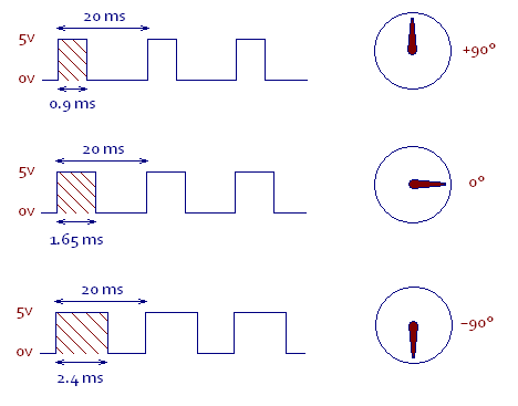
86Diuno’s Servo library and Arduino’s Servo library can output multi-axis PWM (Pulse Width Modulation) signals to control multiple servos and control the angle of the servo by changing the operating period of the PWM (also known as Duty, i.e., the length of HIGH), as shown in the following diagram.

From the above schematic, the PWM cycle of the servo is 20ms, we can input 900us ~ 2400us to rotate the servo from 0 to 180 degrees, and the Servo library of 86Duino and Arduino can send multiple sets of such PWM signals to control multiple servos at the same time. This article to illustrate the PWM jitter refers to the PWM “Duty” will exist irregular jitter phenomenon, the cause of this phenomenon, and the way the control board generates PWM, the following we look at several control boards to generate the PWM signal way:
- PWM signal generation by built-in or external PWM hardware
- Generate PWM signals with software simulation
In first way, the PWM signal is accurate and reliable because it is operated by external or built-in PWM hardware. For example, if we call the analogWrite() function, the PWM hardware will start to operate independently and send out the PWM waveform we specified.
The second method is usually used when the control board does not have built-in or external PWM hardware: software emulation. This method is sometimes used to generate more PWM signals when more PWM signals are needed (e.g., to control a multi-axis RC servo robot). Take 86Duino and Arduino for example. Although both of them have built-in hardware PWM, the built-in Servo library uses software emulation to implement multiple PWM signals in order to output more PWMs to control multiple RC servos.
The PWM signal generated by software simulation is different from the PWM generated by hardware, and most of them will have PWM jitter.
II. Software simulation implementation method
From the above, we know that the PWM simulated by the software will have jitter, but what is the specific cause? The reason lies in the implementation of software simulation.
Software simulation means that we can control the GPIO and Timer on the control board through the program and simulate the PWM output through their joint operation. The GPIO is responsible for controlling the HIGH and LOW pins, and the timer is responsible for issuing interrupts at the Duty and period time points, allowing the program to enter the interrupt subroutine to update the HIGH/LOW state of the GPIO.
What we should pay attention to above is the behavior of “interrupt”. A feature-rich CPU can handle multiple interrupts, but when there are multiple interrupts “at the same time”, the CPU can only handle them one by one in order of priority, that is, if we use a timer interrupt and other interrupts at the same time, the timer interrupt may not be If the timer interrupt and other interrupts occur at the same time, the timer interrupt may not be responded to by the CPU “immediately”, and the CPU must wait until the interrupt with higher priority has been processed before processing the timer interrupt, causing the time to enter the interrupt subroutine to drift each time, which may be long or short. The PWM jitter phenomenon is formed.
The magnitude (range) of PWM jitter is affected by the CPU processing speed, whether there are other interrupts at the same time, interrupt priority, I/O hardware design, etc. The resulting jitter may be large or small.
III. The effect of PWM jitter (Take Arduino Servo library as an example)
On the Arduino Mega 2560, we connect a high precision servo, such as a KONDO KRS4000 series servo, and then use the Servo library to send a PWM with Duty 1500us to this servo, as you can see from the following video, the servo, which has been rotated to 1500us, will have a small vibration due to the jitter of the PWM Duty The servo that has been rotated to 1500us will have a small vibration due to the jitter of PWM Duty (the jitter range of PWM Duty in this example is about 8us).
The high precision servo will respond to the small PWM jitter, but the SG-90 and MG995/996 series, which are commonly found in the market, will not respond to the 8us PWM jitter due to their lower resolution, and therefore do not have the situation in the video.
Next, what if we enable more than 40 PWMs at a time, and then connect a low resolution SG-90 servo instead?
This is because in the Arduino Servo library, the second and third timer interrupts are automatically turned on in order to output more PWMs, causing the two interrupts to interfere with each other and worsening the PWM jitter. The deterioration causes the Duty error range to reach up to 77us, which is sufficient for the low resolution servo to respond and therefore generate jitter.
IV.86Duino Servo Library
As we know from the above, if we can make the PWM jitter range as small as possible, those common servos in the market will be less prone to jitter, so we have made the following improvements in the Servo library of 86Duino (and Servo86 library):
- Once the interrupt subroutine is entered, all interrupts are turned off so that the executive power is not taken away by other high privilege interrupts, effectively reducing PWM jitter.
- Using the built-in PWM hardware timer mechanism, the PWM jitter is effectively reduced by entering the interrupt subroutine early and waiting for the time to arrive.
- Even with 45 PWMs enabled, only one timer interrupt is used, so there is no multiple timers interrupts that can cause PWM jitter to worsen.
Using the above improvements, the 86Duino can still maintain a jitter range of 1us ~ 2us per PWM when 45 PWMs are enabled.
The following table shows the Duty error range measured on the Arduino UNO, Leonardo, Mega, DUE, and 86Duino with 1 PWM enabled using the respective Servo libraries:
| Board | Goal Duty Value | Min Actual measured Value | Max Actual measured Value | Duty error Value |
|---|---|---|---|---|
| Arduino UNO | 1000 us | 1000.04 us | 1006.42 us | 6 ~ 7 us |
| Arduino Leonardo | 1000 us | 1000.04 us | 1007.92 us | 7 ~ 8 us |
| Arduino DUE | 1000 us | 998.200 us | 998.280 us | 1 ~ 2 us |
| Arduino Mega2560 | 1000 us | 1001.12 us | 1008.87 us | 8 ~ 9us |
| 86Duino | 1000 us | 998.64 us | 1001.1 us | 1 ~ 2 us |
The following table shows the Duty error range measured on the Arduino Mega, Arduino DUE, and 86Duino using the respective Servo libraries with 45 PWMs enabled:
| Board | Goal Duty Value | Min Actual measured Value | Max Actual measured Value | Duty error Value |
|---|---|---|---|---|
| Arduino DUE | 1000 us | 998.05 us | 1004.68 us | 2 ~ 5 us |
| Arduino Mega2560 | 1000 us | 1001.09 us | 1076.96 us | 1 ~ 77us |
| 86Duino | 1000 us | 998.70 us | 1001.31 us | 1 ~ 2 us |
From the above, we can see that the 86Duino has improved PWM jitter suppression. In addition, the 86Duino Servo library will automatically switch to hardware PWM output for the pins that are already capable of outputting hardware PWM (marked with a ~ symbol next to the pin) to achieve zero jitters.
Libraries Reference Home
The text of the 86Duino reference is a modification of the Arduino reference and is licensed under a Creative Commons Attribution-ShareAlike 3.0 License. Code samples in the reference are released into the public domain.