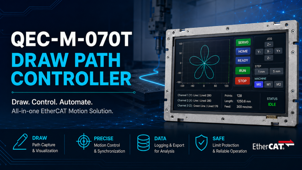
This start guide shows how to build a complete three-axis path-drawing controller on one QEC-M-070T. The operator draws a line on the 7″ touch screen with a finger; the controller smooths the stroke, turns it into a list of waypoints, and hands it to the three axes of one QEC-R11MP3S to draw in real time.
The touch screen, the EtherCAT main device, the path planning and the position logging all run on the same board. No external PC, no PLC, no separate motion control card.
1. At a glance
- Freehand Path Generation — Draw a path directly on the canvas. When the drawing is completed, the program automatically converts the trajectory into a waypoint list of up to 600 points, without requiring any predefined shape.
- Continuous Three-Axis Motion — The X, Y, and Z axes follow the generated trajectory continuously. All motion commands are defined in millimetres, eliminating the need for manual pulse conversion.
- Smooth Path Execution — Upcoming waypoints are queued in a motion buffer, while Motion86 blends adjacent path segments to maintain continuous movement throughout the trajectory.
- Real-Time Limit Switch Protection — Limit switches are monitored during every control cycle. Once triggered, the system immediately performs an emergency stop and remains latched until the activated switch is released.
- Three Operating Pages — Draw for path creation, Jog for manual axis control, and Data for monitoring waypoint and motion status.
2. What You Need
| Item | Notes |
| QEC-M-070T | EtherCAT MDevice with a built-in 7″ 800 × 480 touch panel |
| QEC-R11MP3S × 1 | Primary mechanism : three-axis CiA402 servo module, draws the path |
| QEC-R11MP3S × 2 | Optional mechanism : for the synchronisation check; doesn’t affect the draw path itself |
| 24 V supply | Vs for the system, Vp for the peripherals |
| Limit switches | Wired to a digital input on each axis of the primary mechanism |
| Development environment | 86Duino IDE |
3. Feature Overview
3.1 Draw — drawing and live position
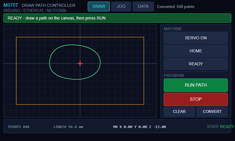
- Amber box — the safe drawing area. Touches outside it are discarded before they are converted into waypoints, which keeps the operator from drawing a path that risks a crash.
- Green line — the converted path, calculated as soon as you lift your finger. The
CONVERTbutton at the bottom right recalculates it. - Red crosshair — where the machine actually is. It appears once the motors are enabled and can be used to monitor the position live.
- Status bar at the bottom — point count, total path length, M0’s live XYZ, and a state chip on the right (
OFF/ON/READY/RUN/JOG/LIMIT).
The banner across the top tells the operator which button to press next, and changes colour with the state: blue when the machine is not ready, green when you can start drawing, amber while running, red when a limit switch has been hit and motion is latched off.
3.2 Jog — manual moves
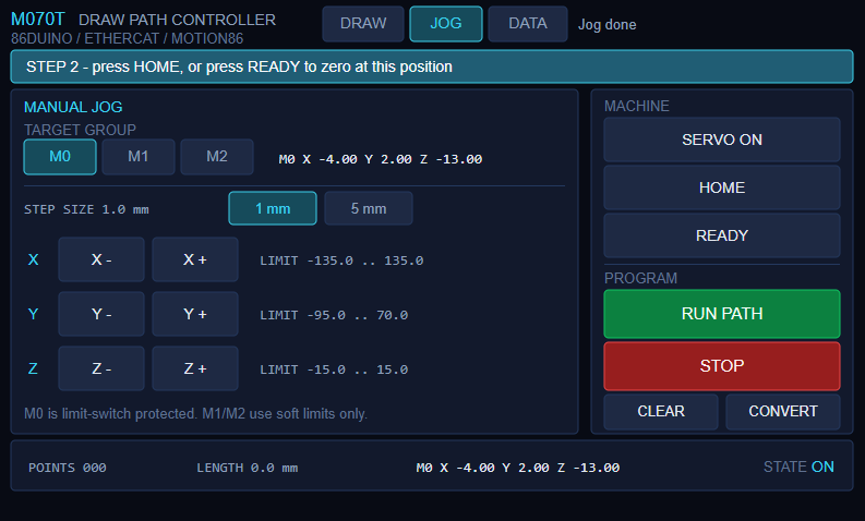
Pick the group to move (M0 / M1 / M2), pick the step size (1 mm or 5 mm), then press X- X+ Y- Y+ Z- Z+. The right-hand side shows the live position of the selected group and each axis’s travel range.
A jog is not sent to the drive as a raw command: the target is first constrained to the allowed range, then issued as an absolute position command — so manual motion gets the same soft-limit protection as program motion.
3.3 Data — waypoint list and execution progress
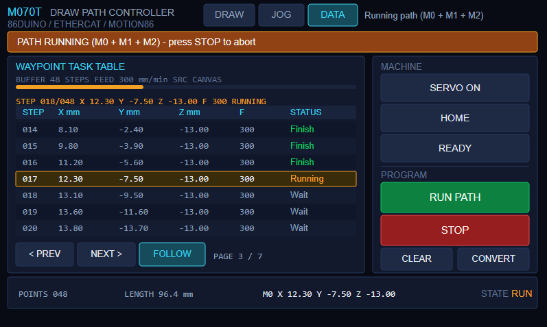
This page lays the whole path out: step number, target X / Y / Z, feedrate, status. Every step passes through Wait → Running → Finish, and while the path runs the page follows along to whichever step is executing.
When the machine draws something other than what you expected, this page tells you whether the problem is in the coordinate conversion or in the mechanism and its parameters.
4. Operating Sequence
| Step | Button | What happens |
| 1 | SERVO ON | First press starts EtherCAT and scans the modules; second press enables the drives |
| 2 | HOME | M0 seeks its home switches, establishes coordinates, backs off. |
| 3 | READY | M0 moves to the working origin; M1 and M2 define their current position as their starting point |
| 4 | RUN PATH | M0 starts drawing; M1 and M2 mirror each displacement |
| 5 | STOP | Halts all the motors at any moment |
5. What Motion86 Does
The real saving in this example comes from the work Motion86 wraps up for you:
- Command in millimetres.
config_PPU()sets “pulses per millimetre” once, and every command afterwards is in millimetres. Change the gear ratio, the screw pitch or the encoder resolution and all you edit is that number. - Soft limits block automatically. With
config_PosLimit()andenableSoftLimit(), an out-of-travel target is blocked before any pulse goes out — no need to write a check before every command. - Homing is built in; you decide how the switch is read. Motion86 runs the sequence and you supply a switch-reading callback, so unusual I/O wiring can still use the rest of the library.
- The path runs as one continuous move. 600 points are fed in through the buffer and Motion86 joins adjacent segments, so it does not become 600 stop-starts.
- One main device controls three mechanisms. Three independent coordinate systems update inside the same 500 µs cycle, and absolute and relative modes can be mixed.
- G-code support.
gcode()can be called at any time and mixed freely withline().
What represents Motion86’s design best is its interface to the drives — the entire coupling is two functions:
void setRemoteTargetPos0(int axis, long pos) {
  if (servo[0][axis]) servo[0][axis]->setTargetPosition(pos);
}
long getRemoteTargetPos0(int axis) {
  if (servo[0][axis]) return servo[0][axis]->getPositionActualValue();
  return 0;
}

machine0.config_CustomActuators_CycleTime(ECAT_CYCLE_TIME);
machine0.config_CustomActuators_Callbacks(setRemoteTargetPos0, getRemoteTargetPos0);
The EtherCAT library speaks in encoder pulses; Motion86 speaks in millimetres, feedrates and G-code; these two small functions join them. Moving to different motors later, or running the whole flow against simulated axes first, mainly means rewriting these two functions — path planning, soft limits, homing and G-code all stay as they are.
6. Safety Design
This example splits crash prevention into three layers, each catching a problem at a different stage:
| Layer | What it catches | Where |
| Screen limits | Unreasonable input | ui.cpp |
| Soft limits | Unreasonable commands | .ino |
| Hardware limits | An actual collision | .ino |
The first two layers are software judgements, and they assume the configured values match the real mechanism; when they do not, the physical switch is all that is left. A triggered limit switch stops motion immediately and latches the state — deliberately so, because a switch being held often bounces, and if recovery relied only on “the switch was released”, the machine could start moving again before the operator has reacted.
7. Resources
- Development guides (PDF): Motion86_DrawPath_Guide_EN | Motion86_DrawPath_Guide_CN
- Example program (ZIP): Motion86_DrawPath
- Video Demonstration: Motion86 Library: Draw Path to Control Axis | EP12 · Multi-axis Control
- 86Duino IDE and QEC software tools: Software
We will continue to deliver robust and innovative EtherCAT automation platforms for smarter, faster machine integration. For more info and sample requests, please write to info@icop.com.tw, call your nearest ICOP Branch, or contact our Worldwide Official Distributor.