EtherCAT – the Ethernet Fieldbus
This section provides an in-depth introduction to EtherCAT (Ethernet for Control Automation Technology). The following information can also be found in the EtherCAT Brochure, available in various languages.
(Source: http://www.ethercat.org/)
With the advancement of communication technology, industrial communication Fieldbus technology has been widely used in industrial control systems. However, Ethernet technology has become one of the most advanced and cost-effective communication technologies, most widely used in various fields, and its related hardware and software technologies are also in rapid development with the popularity of the technology.
EtherCAT (Ethernet Control Automation Technology) is an industrial communication technology based on Ethernet designed to be used in automation (especially in machine automation). It has been growing at an alarming rate with the advantages of Ethernet (universality, high speed, low cost). EtherCAT is mainly used to connect high-speed real-time I/O devices.
Communication Level Comparison:
- Factory Level: < 1000ms. (Ethernet – TCP/IP, etc.) IPC / Server PC / Wireless
- Machine Level: < 100ms. (Modbus / CC-Link, etc.) HMI / Panel PC
- Unit Level: < 5ms. (EtherCAT, etc.) Digital IO / Analog IO / CANOpen Interface
Overview of the EtherCAT protocol
EtherCAT is a real-time Industrial Ethernet technology originally developed by Beckhoff Automation and maintained by the ETG (EtherCAT Technology Group). The EtherCAT protocol disclosed in the IEC standard IEC61158 is suitable for hard and soft real-time requirements in automation technology, test and measurement, and many other applications.
The main focus during the development of EtherCAT was on short cycle times (≤ 100 µs), low jitter for accurate synchronization (≤ 1 µs), and low hardware costs.
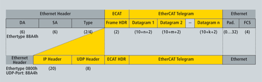
Regarding the OSI network model, the EtherCAT protocol is mainly defined in the Data link Layer and the Application Layer. EtherType can be used in addition to the standard EtherCAT packet (EtherType = 0x88A4) or in UDP format (EtherType = 0x0800) as shown in the figure below.
The EtherCAT text contains mainly the ECAT header (Frame header) and EtherCAT Telegrams.
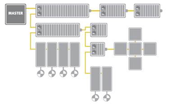
Flexible Topology
Line, tree, star, or daisy chain: EtherCAT supports almost all topologies and offers much flexibility regarding cable types. Industrial Ethernet cable can be used between two nodes up to 100m apart in 100BASE-TX mode; this option enables the connection of devices such as sensors with a single line. Fiber Optics (such as 100BASE-FX) can also be used, for example, for a node distance greater than 100m. The complete range of Ethernet wiring is also available for EtherCAT.
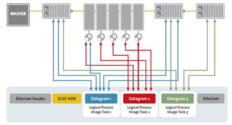
High Speed Performance
Through addressing mode of EtherCAT and the memory control technology “Fieldbus Memory Management unit (FMMU)” performed by EC-Slaves hardware, we can exchange all data synchronically from all ECAT-Slaves on bus by just passing one single internet packet. The types of data include DIO, AIO and servo motor position, etc. Please refer to the diagram below.
The EtherCAT slaves are usually equipped with EtherCAT Slave IC (so-called ESC). With the FMMU technology, the exchange of 1000 unit I/O data can be finished within only 30us. Data for 100 axis servo motor can be exchanged only within 100 us. Please refer to the table below. (According to ETG data)
| Process Data | Update Time |
|---|---|
| 256 distributed digital I/O | 11μs |
| 1000 distributed digital I/O | 30μs |
| 200 channels analog I/O (16 Bits) | 50μs ( =20kHz ) |
| 100 servo axis (8 Bytes Input and output per axis) | 100μs |
| 1 Fieldbus Master-Gateway (1486 Bytes Input and 1486 Bytes output data) | 150μs |
100us data exchange speed for the axis control loop is equal to the control bandwidth of 10 kHz. It is sufficient for doing speed close loop control and even for torque control.
Distributed Clocks for High-Precision Synchronization
In applications with spatially distributed processes requiring simultaneous actions, exact synchronization is particularly important. For example, this is the case for applications in which multiple servo axes execute coordinated movements.
In contrast to completely synchronous communication, whose quality suffers immediately from communication errors, distributed synchronized clocks have a high degree of tolerance for jitter in the communication system. Therefore, the EtherCAT solution for synchronizing nodes is based on such distributed clocks (DC).
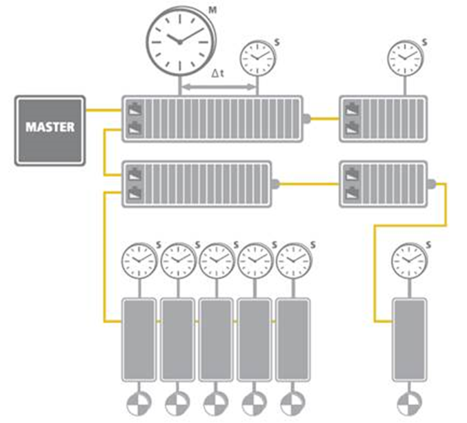
The synchronization mechanism of EtherCAT is based on IEEE-1588 Precision Clock Synchronization Protocol and extends the definition to so-called Distributed-clock (DC). To put it simple, every EtherCAT ESC maintains a hardware-based clock and the minimum time interval is 1 nano-second (64 bits in total). The time maintained by EC-Slave is called Local system time.
With accurate internet time synchronization mechanism and dynamic time compensation mechanism (*1), EtherCAT DC technology can guarantee that the time difference among every EC-Slave local system time is within +/- 20 nano-seconds. The following diagram is a scope view of two slave devices’ output digital signals. We can see that the time difference between the I/O signal from two EC-Slaves is around 20 nano-seconds.
(*1) Please refer to EtherCAT standard document ETG1000.4

Compare traditional and EtherCAT solutions
The popularity of Fieldbus usage in automation technology has led to the widespread use of PC-based control systems. The mainstream architectures are primarily divided into traditional and EtherCAT solutions.
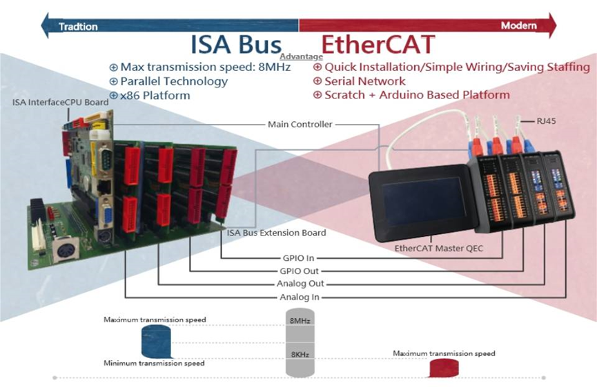
Traditional Solution:
Traditional solutions use hierarchical control systems, usually consisting of several auxiliary systems in a cyclic system, including the actual control task, the field bus system, the local extension bus in the I/O system, or simple local devices for peripherals.
ISA Bus, for example, has been used in the automation field for more than 40 years. It is widely used because of its ability to perform multiple processes such as transmission speeds of 8 MHz, a range of software source code functions, as well as allowing access to various Analog and Digital output.
EtherCAT
EtherCAT solutions have become increasingly popular for automation-related applications in recent years. The connections between master and slave devices can be made via network cables only, making EtherCAT devices stand out from other industrial communication standards due to their fast installation, simple wiring, and labor-saving installation.
Ethernet itself represents a level of technological advancement as in the past, the application types that generally used Fieldbus systems required the system to have good real-time capabilities, adaptable to small data communications, and be economical. EtherCAT meets these requirements for real-time automation technology, testing, and measuring, a variety of other applications.