This guide will show you how to use the EtherCAT Master QEC-M-01P and the Digital I/O Slave QEC-RXXDXX Series.
Notes: QEC’s PoE (Power over Ethernet)
In QEC product installations, users can easily distinguish between PoE and non-PoE: if the RJ45 house is red, it is PoE type, and if the RJ45 house is black, it is non-PoE type.
| Non-PoE type | PoE type |
|---|---|
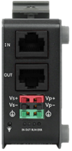 | 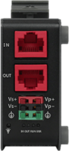 |
PoE (Power over Ethernet) is a function that delivers power over the network. QEC can be equipped with an optional PoE function to reduce cabling. In practice, PoE is selected based on system equipment, so please pay attention to the following points while evaluating and testing:
- The PoE function of QEC is different and incompatible with EtherCAT P, and the PoE function of QEC is based on PoE Type B, and the pin functions are as follows:
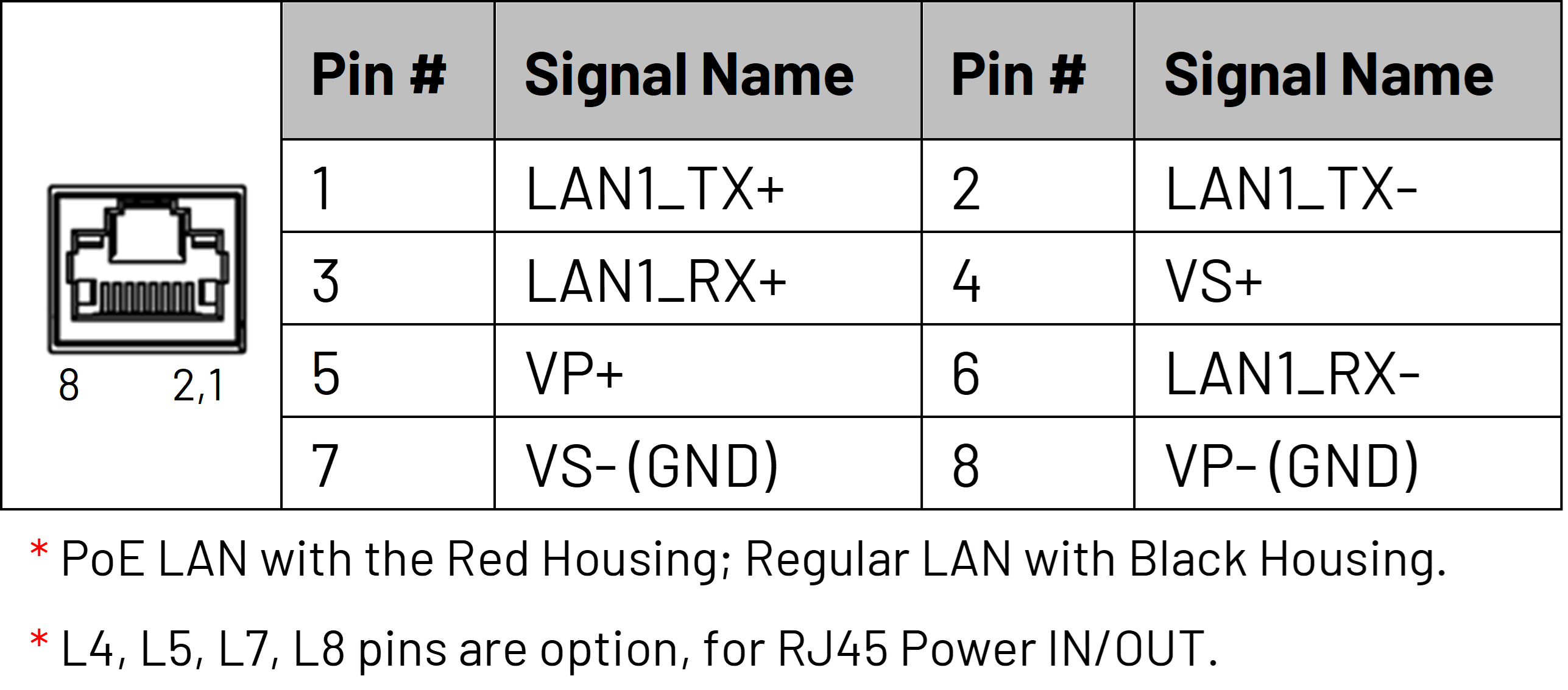
- When connecting PoE and non-PoE devices, make sure to disconnect Ethernet cables at pins 4, 5, 7, and 8 (e.g., when a PoE-supported QEC EtherCAT master connects with a third-party EtherCAT slave).
- QEC’s PoE power supply is up to 24V/3A.
1. Connection and wiring hardware
The following devices are used here:
- QEC-M-01P (EtherCAT Master/PoE)
- QEC-R11D88H-N (EtherCAT Slave 8-ch digital input and 8-ch digital output/PoE)
- 24V power supply
- 24V LED

1.1 QEC-M-01P
QEC EtherCAT master with PoE function.
- Using the EtherCAT Out port (top side) connected to the EtherCAT In port of QEC-R11D88H via RJ45 cable (powered by PoE).
- Connect to Vs+/Vs- and Vp+/Vp- power supplies via EU terminals for 24V power.

1.2 QEC-R11D88H-N
- Connect from VP+ to DO 0+.
- Connect the 24V LED+ terminal to DO 0-.
- Connect the 24V LED- end to the VP-.

2. Software/Development Environment: 86Duino IDE
Download 86duino IDE from https://www.qec.tw/software/.
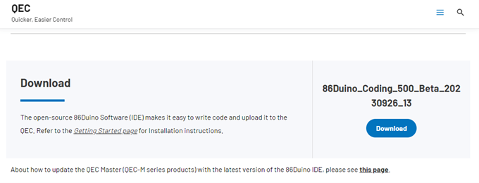
After downloading, please unzip the downloaded zip file, no additional software installation is required, just double-click 86duino.exe to start the IDE.
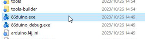
*Note: If Windows displays a warning, click Details once and then click the Continue Run button once.
86Duino Coding IDE 500+ looks like below.

3. Connect to your PC and set up the environment
Follow the steps below to set up the environment:
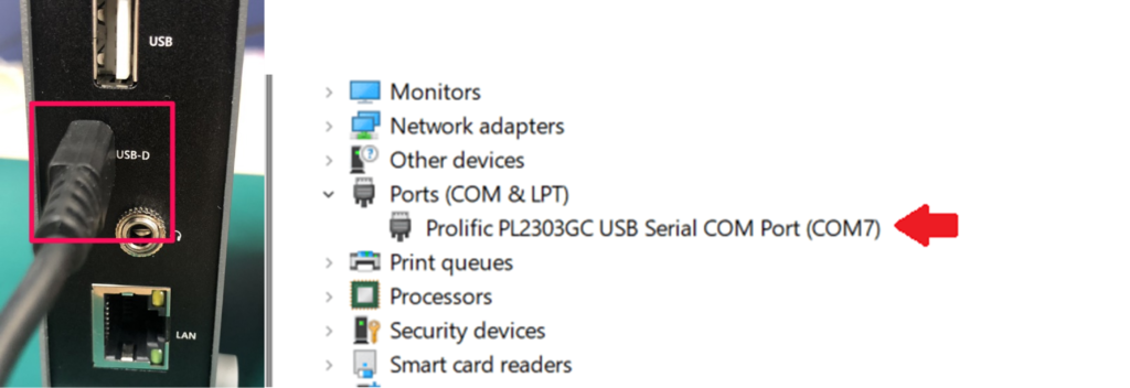
- Connect the QEC-M-01P to your PC via a Micro USB to USB cable (86Duino IDE installed).
- Turn on the QEC power.
- Open “Device Manager” (select in the menu after pressing Win+X) ->” Ports (COM & LPT)” in your PC and expand the ports; you should see that the “Prolific PL2303GC USB Serial COM Port (COMx)” is detected; if not, you will need to install the required drivers.
(For the Windows PL2303 driver, you can download it here)
- Open the 86Duino IDE.
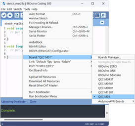
- Select the correct board: In the IDE’s menu, select Tools> Board > QEC-M-01 (or the QEC-M master model you use).
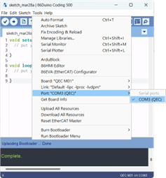
- Select Port: In the IDE’s menu, select Tools > Port and select the USB port to connect to the QEC-M master (in this case, COM3 (QEC)).
3.1 Development Method 1: Write code
The EtherCAT master (QEC-M-01P) and the Digital IO slave (QEC-R11D88H-N) can be configured and programmed via the EtherCAT library in the 86Duino IDE.
The Arduino development environment has two main parts: setup() and loop(), which correspond to initialization and main programs. Before operating the EtherCAT network, you must configure it once. The process should be from Pre-OP to OP mode in EtherCAT devices.
The following example is setting Pin0 of Digital Output to HIGH for 4 seconds and then changing it to LOW for 1 second.
3.1.1 For QEC slaves
When using QEC Slave, you can use the dedicated QEC Ethercat Slave Library. For example, QEC-R11D88H can be used EthercatDevice_QECRXXD Class. The example code is as follows:
#include "Ethercat.h" // Include the EtherCAT Library

EthercatMaster master; // Create an EtherCAT Master Object
EthercatDevice_QECR11D88H slave; // Create an EtherCAT Slave Object for QEC-R11D88H

// put your setup code here, to run once:
void setup() {
    // Initialize the EtherCAT Master. If successful, all slaves enter PRE-OPERATIONAL state
    master.begin();

    // Attach the QEC-R11D88H slave device to the EtherCAT Master at position 0
    slave.attach(0, master);

    // Start the EtherCAT Master. If successful, all slaves enter OPERATIONAL state
    // The parameter 1000000 sets the cycle time in nanoseconds
    master.start(1000000, ECAT_SYNC);
}

// put your main code here, to run repeatedly:
void loop() {
    // Set digital output at pin 0 to HIGH
    slave.digitalWrite(0, HIGH);
    delay(4000); // Wait for 4 seconds

    // Set digital output at pin 0 to LOW
    slave.digitalWrite(0, LOW);
    delay(1000); // Wait for 1 second
}
3.1.2 For third-party slaves
When using a non-QEC slave, you can use the EthercatDevice_Generic function, which can be referenced EthercatDevice Class. The example code is as follows and can also be used in QEC-R11D88H.
#include "Ethercat.h" // Include the EtherCAT Library

EthercatMaster master; // Create an EtherCAT Master Object
EthercatDevice_Generic slave; // Create an EtherCAT Slave Object

// put your setup code here, to run once:
void setup() {
    // Initialize the EtherCAT Master. If successful, all slaves enter PRE-OPERATIONAL state
    master.begin();

    // Attach the QEC-R11D88H slave device to the EtherCAT Master at position 0
    slave.attach(0, master);

    // Start the EtherCAT Master. If successful, all slaves enter OPERATIONAL state
    // The parameter 1000000 sets the cycle time in nanoseconds
    master.start(1000000, ECAT_SYNC);
}

// put your main code here, to run repeatedly:
void loop() {
    // Write a HIGH value to a bit in the Process Data Output at index 0
    slave.pdoBitWrite(0, HIGH);
    delay(4000); // Wait for 4 seconds

    // Write a LOW value to the same bit in the Process Data Output at index 0
    slave.pdoBitWrite(0, LOW);
    delay(1000); // Wait for 1 second
}
Note: Once the code is written, click on the toolbar to ![]() compile, and to confirm that the compilation is complete and error-free, you can click
compile, and to confirm that the compilation is complete and error-free, you can click ![]() to upload. The program will run when the upload is complete, and the LED will start flashing.
to upload. The program will run when the upload is complete, and the LED will start flashing.
4. Development Method 2: Use 86EVA with code
86EVA is a graphical EtherCAT configurator based on the EtherCAT Library in the 86Duino IDE and is one of the development kits for 86Duino. The user can use it to configure the EtherCAT network quickly and start programming.
The following example is setting Pin0 of Digital Output to HIGH for 4 seconds and then changing it to LOW for 1 second.
Step 1: Turn on 86EVA and scan
The 86EVA tool can be opened via the following buttons.
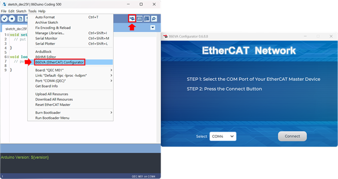
Once you have confirmed that the correct COM port has been selected of QEC-M-01P, press the Connect button to start scanning the EtherCAT network.

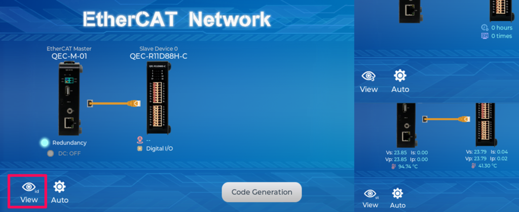
The connected devices will be displayed after the EtherCAT network has been scanned.
Press the “View” button in the lower left corner to check the device’s status.
Step 2: Set the parameters
Press twice on the scanned device image to enter the corresponding parameter setting screen.
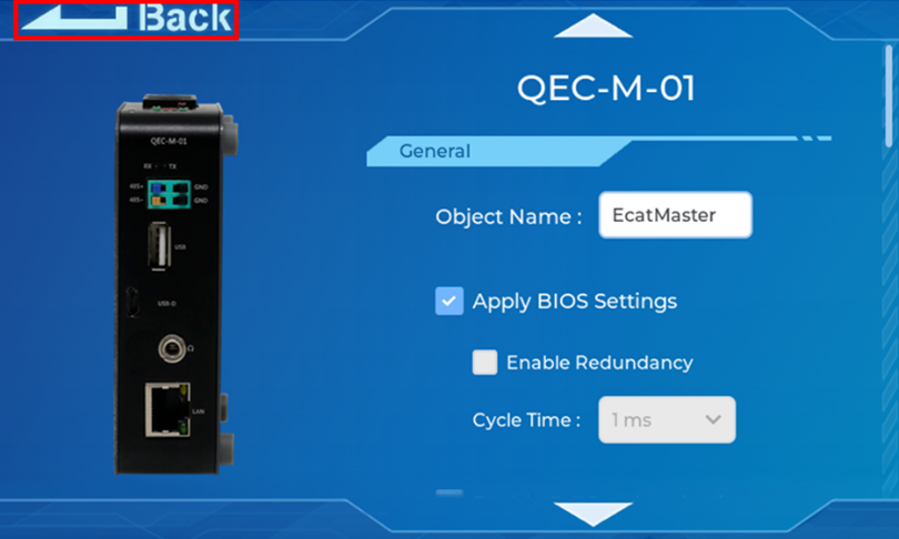
QEC-M-01
Press twice on the image of the QEC-M-01 to see the parameter settings.
If you are developing for the first time, please use the preset settings first and click “Back” in the upper left corner to return.
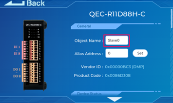
QEC-R11D88H-N
Press twice on the image of the QEC-R11D88H to see the parameter settings.
Continue down to the “Digital Output Pin Mapping” area. Among them, we select “Virtual Pin D0” in the drop-down box of DQ00 of Digital Output Pin Mapping and click “Back” in the upper left corner to return.
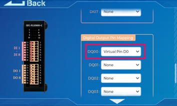
This action is to set the Digital Output Pin0 of QEC-R11D88H to the virtual D0 pin of EVA.
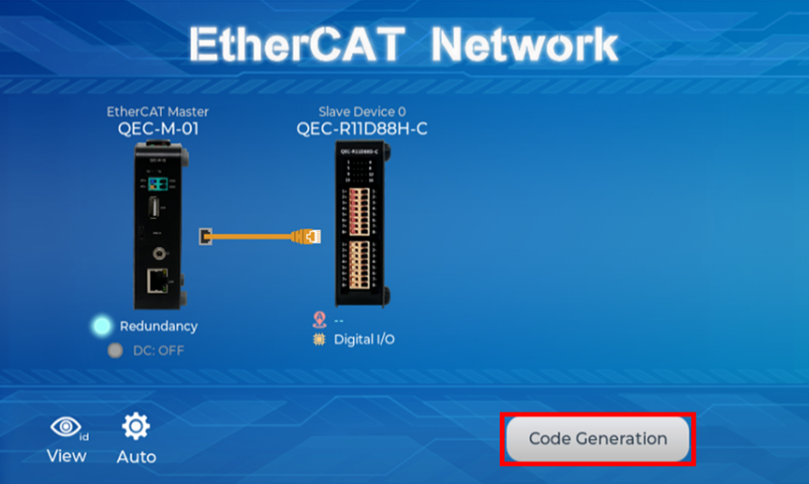
Step 3: Generate the code
Once you’ve set your device’s parameters, go back to the home screen and press the “Code Generation” button in the bottom right corner.
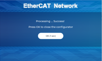
When you’re done, double-click the OK button to turn off 86EVA, or it will close in 10 seconds.
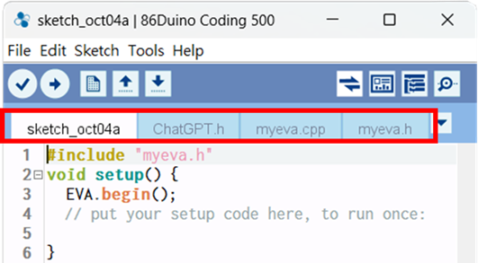
The generated code and files are as follows:
- sketch_oct04a: Main Project (.ino, depending on your project name)
- ChatGPT.h: Parameters to provide to ChatGPT referred
- myeva.cpp: C++ program code of 86EVA
- myeva.h: Header file of 86EVA
Additional note: After 86EVA generates code, the following code will be automatically generated in the main program (.ino), and any of them missing will cause 86EVA not to work.
#include “myeva.h”: Include EVA Header fileEVA.begin()insetup();: Initialize the EVA function
Step 4: Write the code
The following example is setting the D0 pin of EVA (Pin0 for Digital Output) to HIGH for 4 seconds and then changing it to LOW for 1 second.
#include "myeva.h" // Include EVA function

void setup() {
  EVA.begin(); // Initialize EVA function.
  // put your setup code here, to run once:
}

void loop() {
    // put your main code here, to run repeatedly:
    // Set EVA D0 pin to HIGH
    EVA.digitalWrite(0, HIGH);
    delay(4000); // Wait for 4 seconds

    // Set EVA D0 pin to HIGH
    EVA.digitalWrite(0, LOW);
    delay(1000); // Wait for 1 second
}
Note: Once the code is written, click on the toolbar to ![]() compile, and to confirm that the compilation is complete and error-free, you can click
compile, and to confirm that the compilation is complete and error-free, you can click ![]() to upload. The program will run when the upload is complete, and the LED will start flashing.
to upload. The program will run when the upload is complete, and the LED will start flashing.
5. Troubleshooting
5.1 QEC-M-01 cannot successfully upload the code
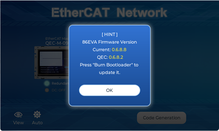
When you are unable to successfully upload code, please open 86EVA to check if your QEC EtherCAT Master’s environment is abnormal. As shown in the figure below, please try updating your QEC EtherCAT Master’s environment, which will include the following three items: Bootloader, EtherCAT firmware, and EtherCAT tool.
Now, we will further explain how to proceed with the update:
Step 1: Setting up QEC-M
- Download and install 86Duino IDE 500 (or a newer version): You can download it from Software.
- Connect the QEC-M: Use a USB cable to connect the QEC-M to your computer.
- Open 86Duino IDE: After the installation is complete, open the 86Duino IDE software.
- Select Board: From the IDE menu, choose “Tools” > “Board” > “QEC-M-01” (or the specific model of QEC-M you are using).
- Select Port: From the IDE menu, choose “Tools” > “Port” and select the USB port to which the QEC-M is connected.
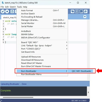
Step 2: Click “Burn Bootloader” button
After connecting to your QEC-M product, go to “Tools”> “Burn Bootloader”. The currently selected QEC-M name will appear. Clicking on it will start the update process, which will take approximately 5-20 minutes.
- QEC-M-01:
Step 3: Complete the Update
After completing the above steps, your QEC-M has been successfully updated to the latest version of the development environment.
For more information and sample requests, please write to info@qec.tw, call your nearest ICOP branch, or contact our official global distributor.