EtherCAT (Ethernet for Control Automation Technology) is a real-time industrial Ethernet protocol originally developed by Beckhoff Automation and now maintained by the EtherCAT Technology Group (ETG). It is standardized under IEC 61158 and designed for applications where communication speed, synchronization precision, and deployment flexibility are critical requirements.
(出典 http://www.ethercat.org/)
This page explains what EtherCAT is, why it outperforms traditional fieldbus protocols, and what performance levels it delivers in real industrial deployments.
1. Where EtherCAT fits in industrial communication
Industrial communication operates across three distinct levels, each with different response time requirements:
| Communication Level | Response time | Protocol Examples | Typical Use |
|---|---|---|---|
| Factory Level | < 1000ms | Ethernet TCP/IP, OPC UA | ERP, MES, Cloud, SCADA |
| Machine Level | < 100ms | Modbus, CC-Link, PROFIBUS | HMI, Panel PC, PLC |
| Unit Level | < 5ms | EtherCAT, PROFINET IRT | Real-time I/O, Motion Control |
EtherCAT operates at the unit level — the layer closest to the machine, where response time directly affects control quality. Traditional protocols like Modbus and CC-Link were designed for machine-level communication at 1–100ms. EtherCAT achieves cycle times below 100µs, making it suitable for applications that Modbus-class protocols cannot support.
2. Four reasons engineers choose EtherCAT
2.1 Cycle times under 100µs — fast enough for motion control
EtherCAT’s minimum cycle time is 100µs, with practical deployments commonly running at 125µs or 250µs. A 100µs cycle time corresponds to a control loop bandwidth of 10 kHz — sufficient for both speed and torque control of servo axes.
Traditional fieldbus systems operating at 1–100ms cycle times cannot support this class of application. The difference is not a performance increment; it is a categorical boundary between systems that can and cannot perform real-time coordinated motion control.
2.2 ±20ns synchronization across distributed nodes
EtherCAT uses Distributed Clocks (DC), a synchronization mechanism based on IEEE-1588 Precision Clock Synchronization Protocol. Every EtherCAT device maintains a hardware clock with 1 nanosecond resolution. Through automatic time compensation, all clocks across the network are aligned to within ±20 nanoseconds of each other — regardless of network size or cable length.
In practice, this means two servo axes located 120 meters apart can trigger within 20 nanoseconds of each other. This level of precision is what makes coordinated multi-axis motion possible without a centralized motion controller managing all timing.
In contrast, systems relying on software-based synchronization experience jitter that varies with CPU load and communication errors. EtherCAT’s hardware-based DC mechanism is not affected by these variables.
2.3 Flexible topology — line, tree, star, or daisy chain
EtherCAT supports all standard network topologies. Devices connect using standard Ethernet cable (minimum CAT5) in any combination of line, tree, star, or daisy chain configurations. Nodes up to 100 meters apart connect directly in 100BASE-TX mode without repeaters.
For installations requiring longer distances — for example, connecting equipment across a large factory floor — fiber optic segments (100BASE-FX) extend reach to several kilometers. Multiple junction modules can be combined to create star topologies for complex machine architectures.
This flexibility means the network layout adapts to the physical requirements of the machine. There is no need to design machine layout around the constraints of the communication protocol.
2.4 Standard Ethernet hardware — no proprietary infrastructure
EtherCAT uses standard Ethernet hardware throughout. There are no proprietary cables, no specialized switches required between nodes, and no dedicated interface cards needed in most configurations. The physical layer is identical to ordinary office or industrial Ethernet.
This has a direct impact on both initial deployment cost and long-term maintenance. Replacement hardware is widely available, and engineering teams already familiar with Ethernet do not need to learn a proprietary wiring standard.
3. EtherCAT vs traditional fieldbus — a practical comparison
| Traditional Fieldbus | EtherCAT | |
|---|---|---|
| Cable type | Proprietary (varies by protocol) | Standard CAT5 Ethernet |
| サイクルタイム | 1–100ms | ≤ 100µs |
| Synchronization | Software-based, limited precision | Hardware DC, ±20ns across all nodes |
| Topology | Fixed, protocol-dependent | Line, tree, star, daisy chain |
| Node distance | Protocol-dependent | Up to 100m per segment (copper), km (fiber) |
| Real-time I/O updates (1000 points) | ~1ms or more | 30µs |
| Infrastructure cost | Proprietary components required | Standard Ethernet hardware |
The shift from traditional fieldbus to EtherCAT is not simply a speed upgrade. It changes what kinds of applications are architecturally possible — enabling distributed motion control, high-channel-count I/O at sub-millisecond update rates, and network topologies that match machine geometry rather than constrain it.
4. EtherCAT performance reference data
The following update times are based on benchmark data published by the EtherCAT Technology Group (ETG) and reflect typical cycle times achievable with standard EtherCAT hardware.
| プロセスデータ | Update Time |
|---|---|
| 256点の分散型デジタルI/O | 11μs |
| 1000点の分散型デジタルI/O | 30μs |
| 200チャンネルアナログI/O(16ビット) | 50μs ( =20kHz ) |
| 100サーボ軸(1軸あたり8Byte入出力) | 100μs |
| 1 フィールドバス・マスター・ゲートウェイ (1486バイトの入力データおよび1486バイトの出力データ) | 150μs |
A 100µs update cycle for 100 servo axes corresponds to a control loop bandwidth of 10 kHz — the threshold for torque control applications in servo motion systems.
4.1 Distributed Clocks for High-Precision Synchronization
フィールドに分散したプロセスに同期動作が必要となるアプリケーションでは高精度な同期が特に重要です。例えば複数のサーボ軸が同期動作を行うようなアプリケーションがこれに当てはまります。
通信エラーが発生するとすぐに品質が低下する完全同期通信方式とは対照的に、分散同期クロック方式は、通信システムのジッターに対して広い許容範囲を備えています。
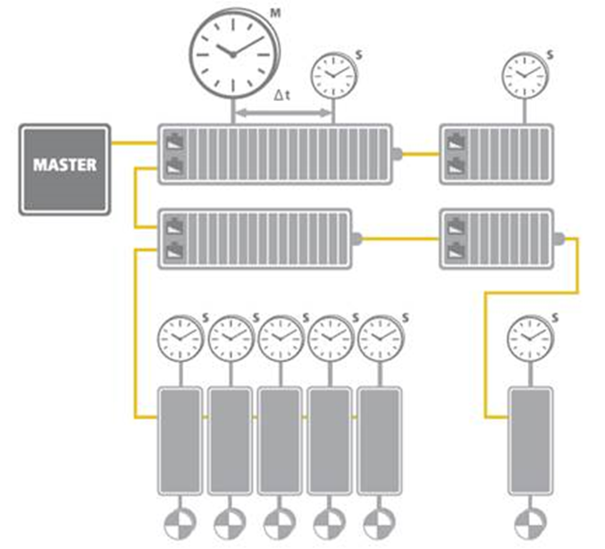
The synchronization mechanism of EtherCAT is based on IEEE-1588 Precision Clock Synchronization Protocol and extends the definition to the so-called Distributed-clock (DC). To put it simply, every EtherCAT ESC maintains a hardware-based clock, and the minimum time interval is 1 nanosecond (64 bits in total). The time maintained by EC-Slave is called Local system time.
With an accurate internet time synchronization mechanism and a dynamic time compensation mechanism (*1), EtherCAT DC technology can guarantee that the time difference among every EC-Slave local system time is within +/- 20 nano-seconds. The following diagram is a scope view of the two slave devices’ output digital signals. We can see that the time difference between the I/O signal from two EC-Slaves is around 20 nanoseconds.
(*1) Please refer to the EtherCAT standard document ETG1000.4

5. EtherCAT protocol overview
EtherCAT is defined primarily at the Data Link Layer and Application Layer of the OSI model. It uses a standard Ethernet frame (EtherType 0x88A4) or UDP format (EtherType 0x0800). The frame contains an ECAT header followed by one or more EtherCAT telegrams.
The key mechanism that enables EtherCAT’s performance is on-the-fly processing: each device reads and writes its data to the Ethernet frame as it passes through, without waiting for the frame to be received and retransmitted. This is handled by the EtherCAT Slave Controller (ESC) hardware and its Fieldbus Memory Management Unit (FMMU), which maps device process data directly into the Ethernet frame in hardware rather than software.
This architecture means that a single Ethernet frame can carry the process data of all devices on the network simultaneously, updated in a single pass — rather than requiring individual point-to-point exchanges.
6. Next step
If you are evaluating EtherCAT for a machine control project and want to understand how to build a working system around it — including MDevice selection, SubDevice I/O expansion, and software development — see the following page:
Read next: The Advantages of Using the QEC EtherCAT Platform → (https://www.qec.tw/ethercat/the-advantages-of-using-the-qec-family-of-ethercat-products/)