[QEC Tutorial]
For the full tutorial, see EtherCAT Library Example: QEC Digital Input/Output.
Digital Input/Output
This chapter will combine the Digital Output and Digital Input together.
The external LED will be blinked through QEC-R11D0F first, and then the LED status will be received through QEC-R11DF0 and printed out through Serial Port.
Hardware
- QEC-M-01
- QEC-R11DF0: EtherCAT 16 Channel Digital Input Slave Module
- QEC-R11D0F: EtherCAT 16 Channel Digital Output Slave Module
- Others: 24V LED
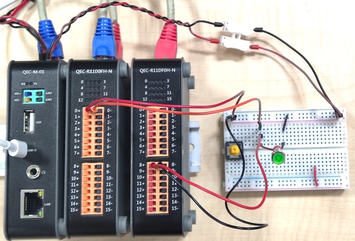
Circuit
Please first connect the EtherCAT Out network on the QEC-M to the EtherCAT In network of the QEC-R11D0F, and the EtherCAT Out network of the QEC-R11D0F to the EtherCAT In network of the QEC-R11DF0.
This example will use Vp power as the power source for QEC-R11D0F Pin0 by using Pin8 of QEC-R11DF0 as the receive signal pin.
- Vp power is connected to QEC-R11D0F Pin0+
- QEC-R11D0F Pin0- connected to the LED VCC
- LED GND to Pin8+ of QEC-R11DF0
- Pin8- of QEC-R11DF0 is connected back to GND of Vp power supply
As shown in the figure.
Code
After constructing the circuit, you need to set the EtherCAT master and slave object names.
For this integration example, the Digital Output is set as the first slave slave0 and the Digital Input is set as the second slave slave1.
EthercatMaster master;
EthercatDevice_QECR11D0FH slave0; // Depend on your QEC device name
EthercatDevice_QECR11DF0H slave1; // Depend on your QEC device name
In the main loop, we first set Pin0 of QEC-R11D0FS to High, read Pin8 of QEC-R11DF0D, and print out in Serial Port with a delay of 4000ms; after that, we set Pin0 of QEC-R11D0FS to Low, read Pin8 of QEC-R11DF0D, and print out in Serial Port with a delay of 1000ms, and the program code will be as follows.
slave0.digitalWrite(0, HIGH);
delay(10);
Serial.println(slave1.digitalRead(8));
delay(4000);
slave0.digitalWrite(0, LOW);
delay(10);
Serial.println(slave1.digitalRead(8));
delay(1000);
Among them, between digitalWrite and digitalRead, we need to add delay(10) to wait for the Input PDO to be updated.
Example
#include "Ethercat.h"

EthercatMaster master;
EthercatDevice_QECR11D0FH slave0; // Depend on your QEC device name
EthercatDevice_QECR11DF0H slave1; // Depend on your QEC device name

void setup(void) {
    Serial.begin(115200);
    /* EtherCAT */
    master.begin();
    slave0.attach(0, master);
    slave1.attach(1, master);
    master.start();
}

void loop() {
    slave0.digitalWrite(0, HIGH);
    delay(10);
    Serial.println(slave1.digitalRead(8));
    delay(4000);
    slave0.digitalWrite(0, LOW);
    delay(10);
    Serial.println(slave1.digitalRead(8));
    delay(1000);
}
Learn More
You can find more information about the basic QEC applications in the EtherCAT application.
You can also explore Language or Libraries for a more detailed collection of 86Duino IDE programming.