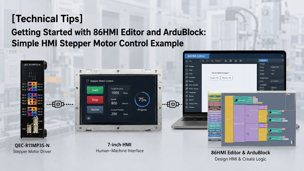
This example shows how to quickly implement stepper motor control on the 86Duino platform, covering HMI button design with 86HMI Editor and drag-and-drop programming with ArduBlock.
For users who are new to the platform, a step-by-step guide is also available to help you set up the development environment and get started with your first project: Getting started with the 86Duino
1. Hardware Setup
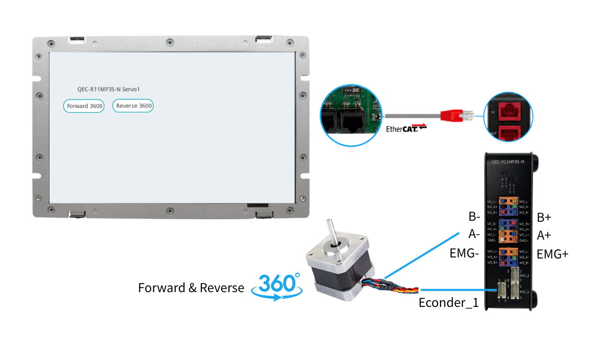
The hardware setup uses the QEC-M-070T as the EtherCAT MDevice controller and the QEC-R11MP3S-N as the SubDevice stepper motor driver:
- QEC-M-070T – EtherCAT MDevice HMI solutions used for interface design and control logic execution
- QEC-R11MP3S-N – EtherCAT motion control with 3-axis Stepper Motor Controller
- 24V power supply
- Ethernet cable (for EtherCAT communication)
2. Implementation Steps
The implementation process can be divided into three main steps.
- First, use 86EVA to scan and configure the EtherCAT devices. This step ensures that all connected EtherCAT slaves are correctly detected and properly configured.
- Next, design the HMI interface using 86HMI Editor. The interface can include buttons, text, and other visual elements required for motion control.
- Finally, create the control logic using ArduBlock. By combining the EtherCAT configuration and HMI interface, the function can be completed and operated through the HMI.
2.1 Step 1 – 86EVA Configurator
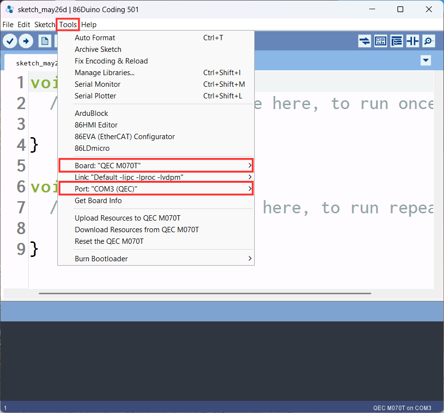
- Set up the development board and port to be used in tool option
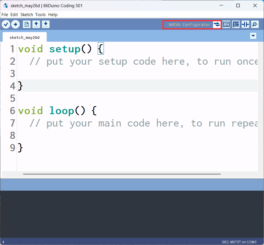
- Click the 86EVA Configuration Tool
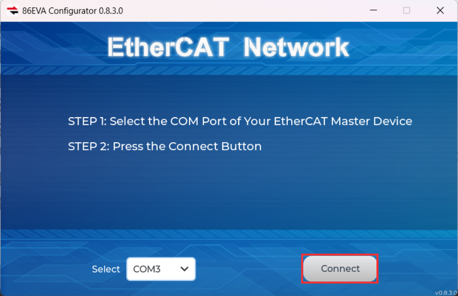
- Click to Connect to scan the device
- Scanning Device
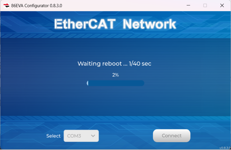
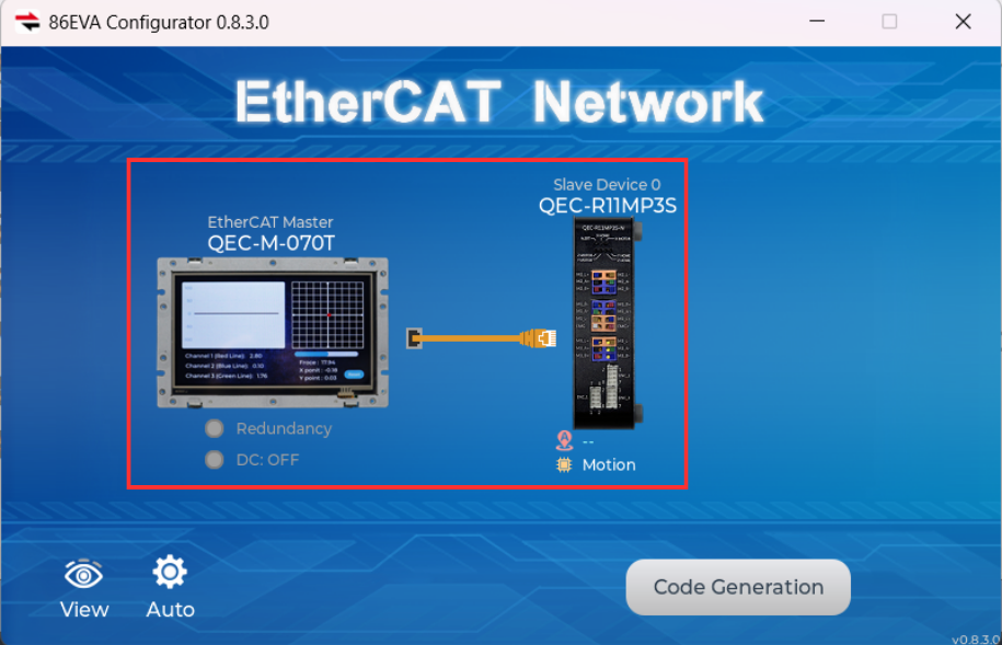
- Configure QEC-M-070T and QEC-R11MP3S-N devices in 86EVA network
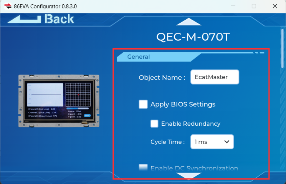
- Set up the QEC-M-070T Parameters (As shown in the illustration)
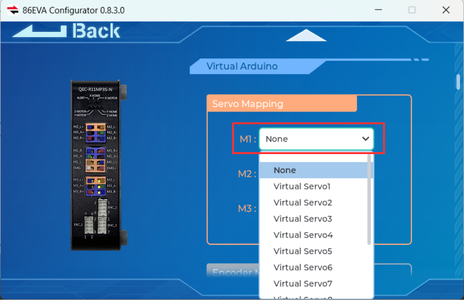
- Set up the QEC-R11MP3S-N M1 in the servo mapping
- Set up the servo 1 parameters (As shown in the illustration)
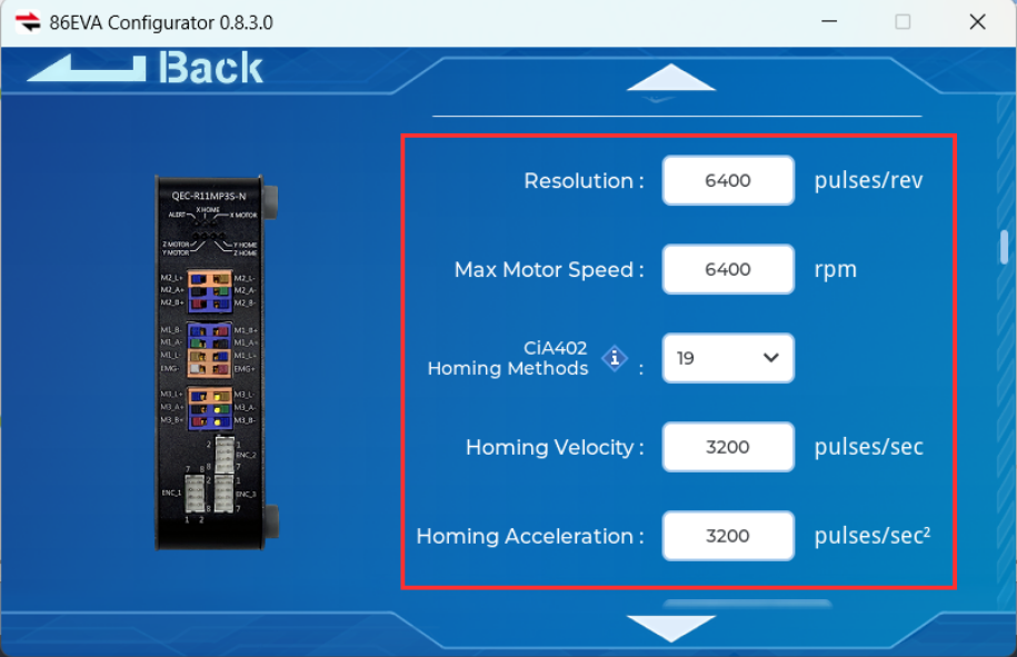
- Back to 86EVA to click Code Generation
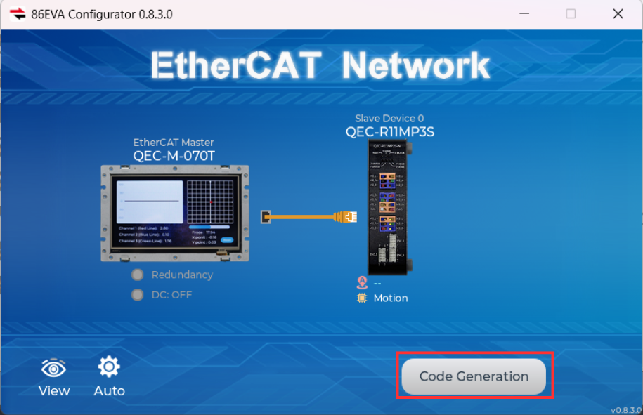
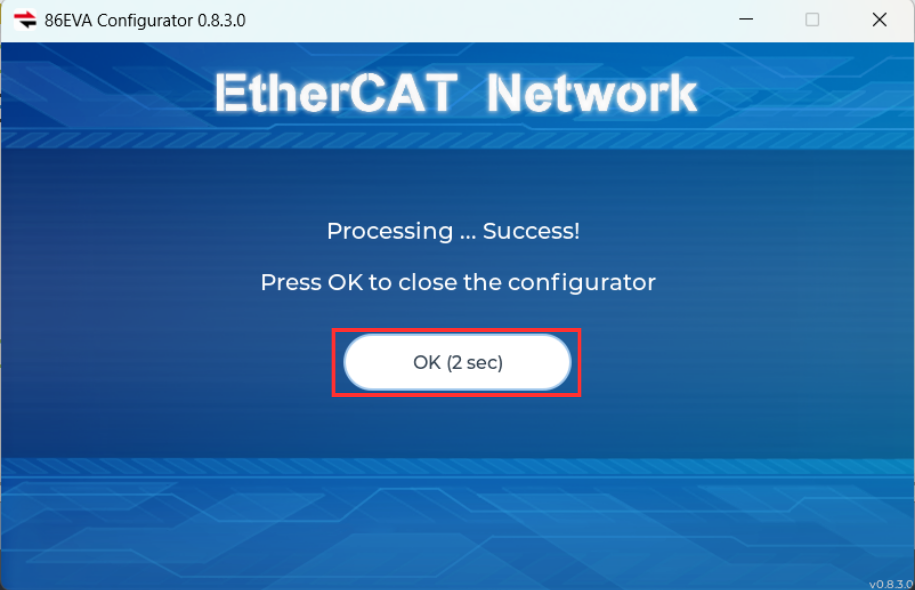
- Scanning is complete and click OK to confirm
2.2 Step 2 – 86HMI Editor UI Design
- Click the 86HMI Editor Tool
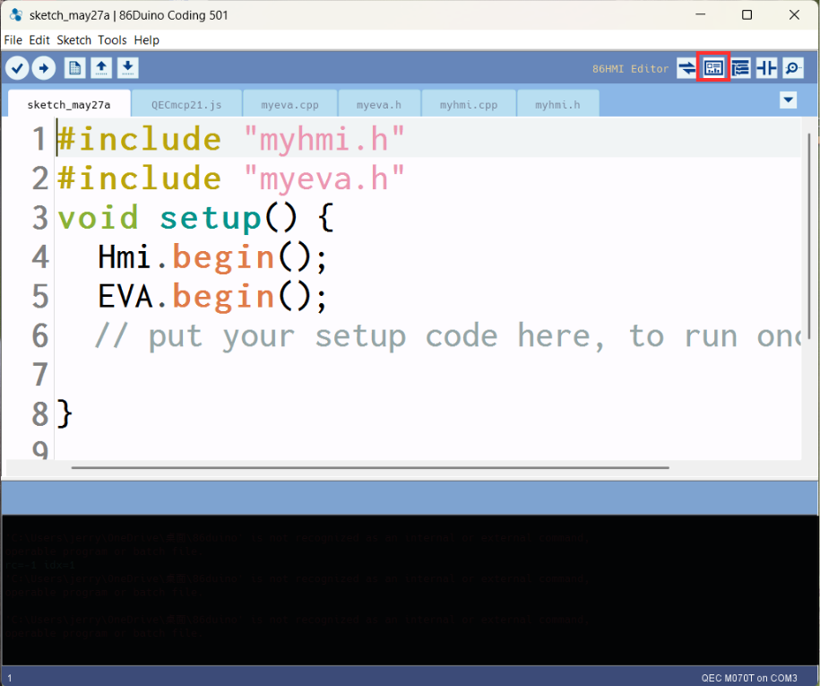
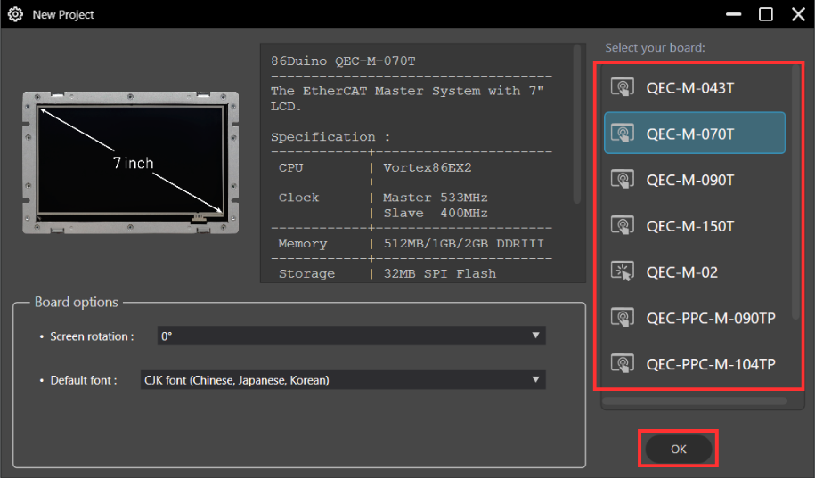
- Select the board and Click OK
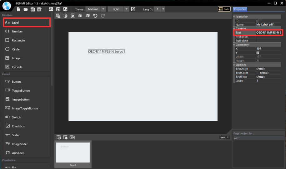
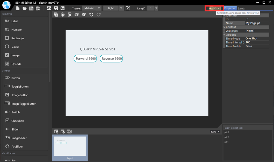
- Edit Text: Label > Text (Type the text inside the field)
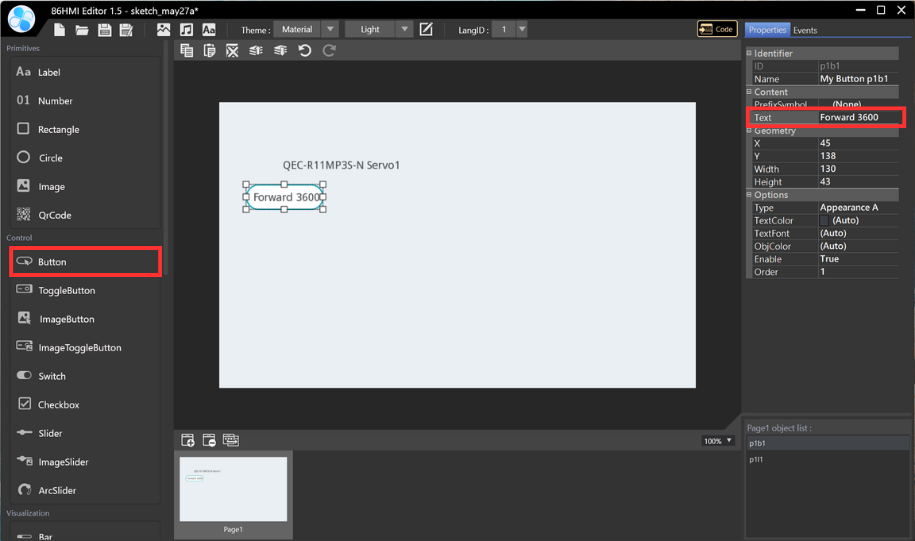
- Add control button: Button (p1b1) > Edit the button text (Type the text inside the field)
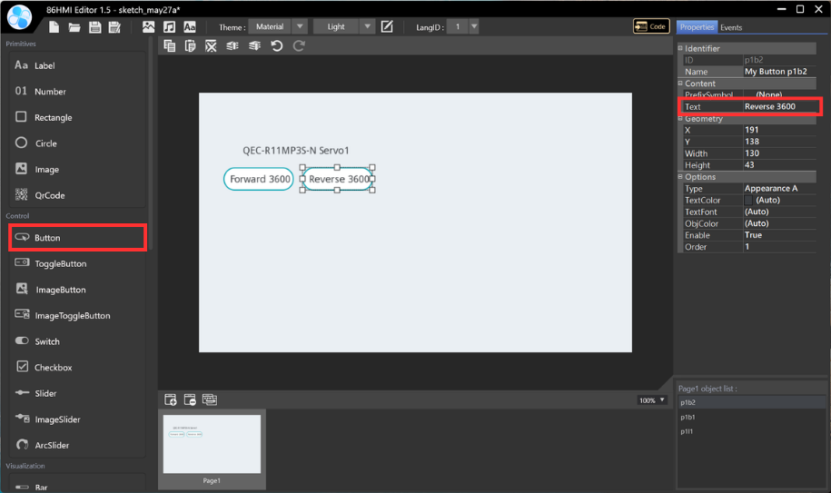
- Add control button: Button (p1b2) > Edit the button text (Type the text inside the field)
- Upload to Generate Example Content
2.3 Step 3 – ArduBlock Programming
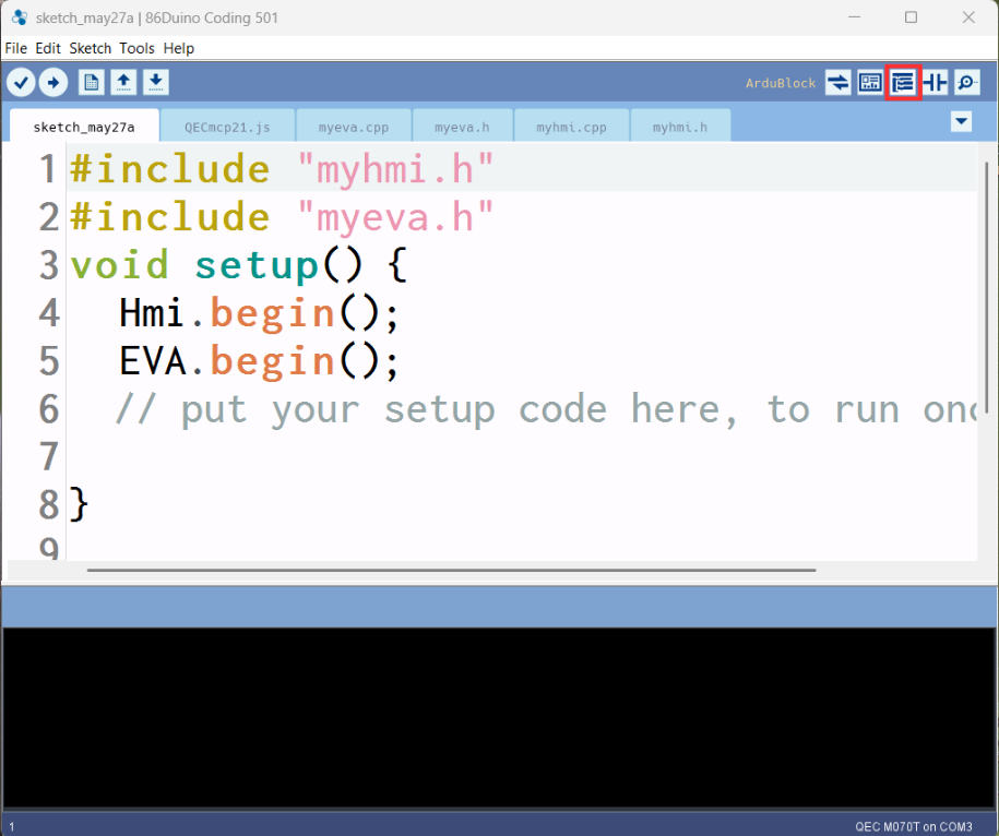
- Click the ArduBlock Tool
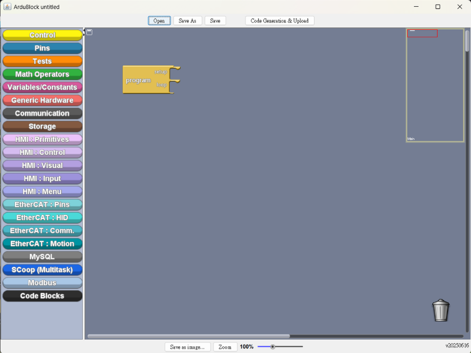
- ArduBlock Work Area
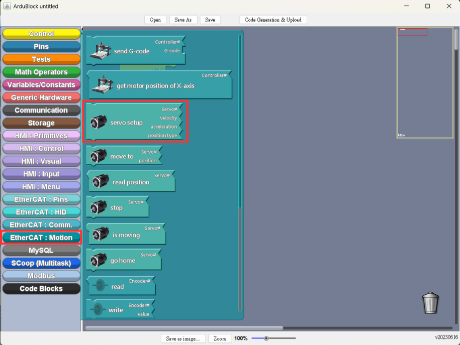
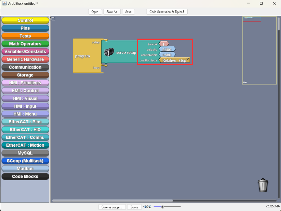
- EtheCAT Motion Setup: EtherCAT.Motion > servo setup
- Setting the parameter (As shown in the illustration)
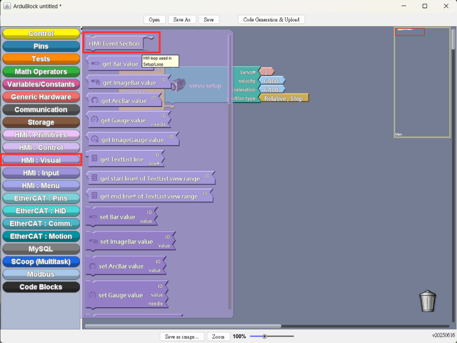
- Add HMI Visual Block: HMI.Visual > HMI Event Section
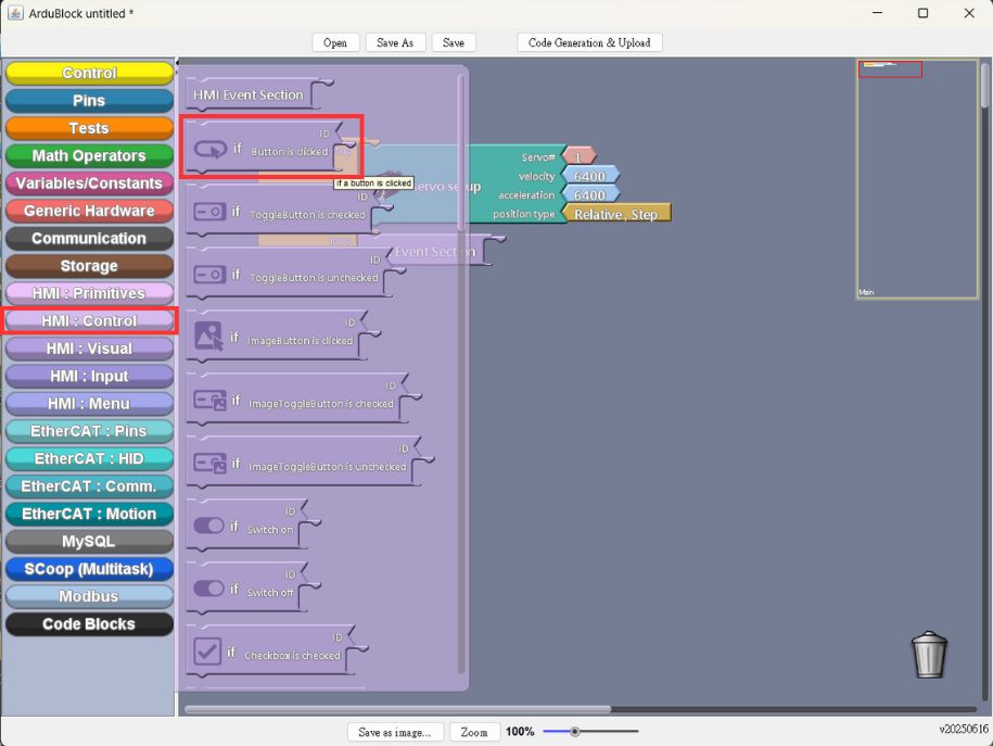
- Add Control Button: HMI.Control > if Button is clicked
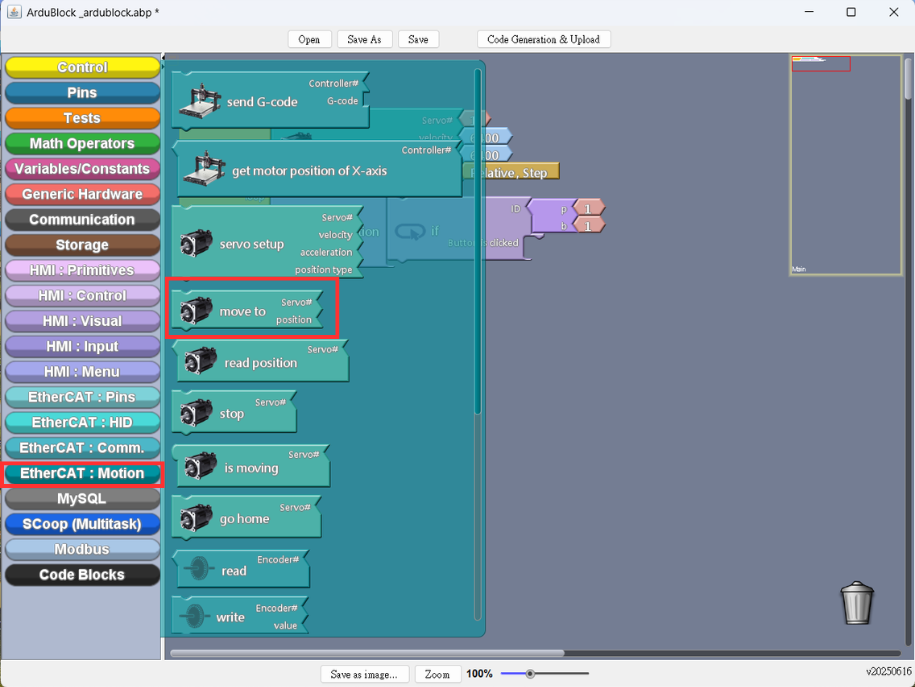
- EtheCAT Motion Setup: add move to block
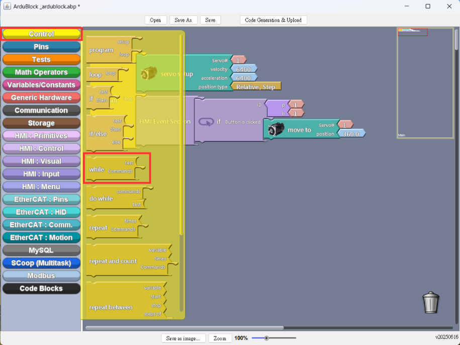
- Add Condition Block: while block
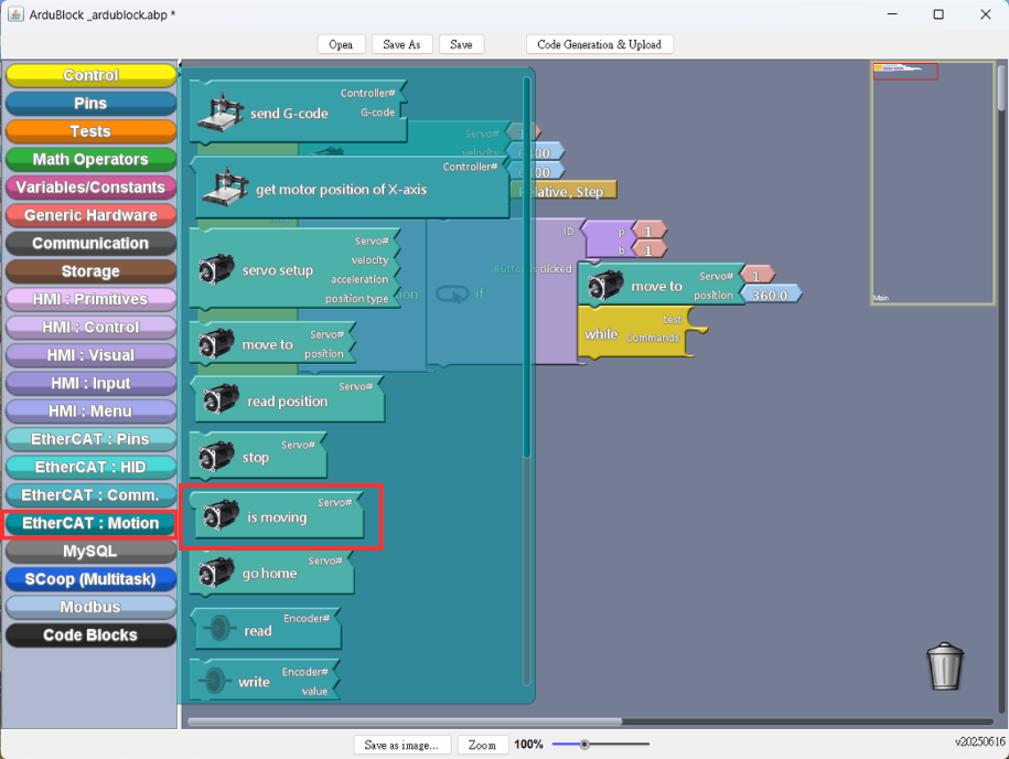
- EtheCAT Motion Setup: add is moving
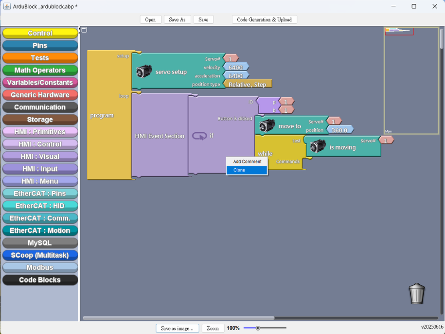
- Right-click to clone the whole control block (As shown in the illustration)
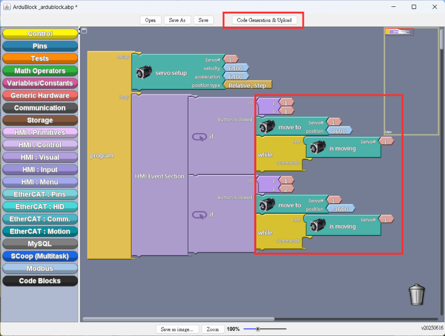
- Set up the parameters, and upload to Generate Example Content
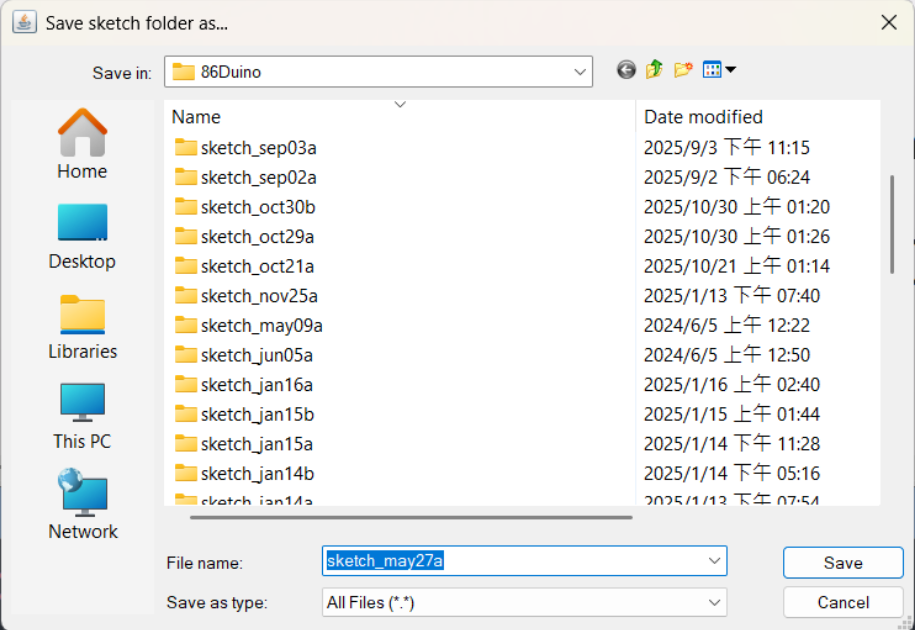
- Save draft (Please select the folder where you want to save it)
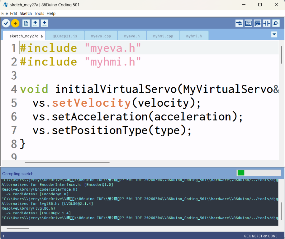
- Upload and compile the sketch
3. Demonstration Result
- Results Presentation
For more info and sample requests, please write to info@icop.com.tw, call your nearest ICOP Branch, or contact our Worldwide Official Distributor.