Want your machine network and plant network to share data without adding a gateway or router?
The QEC-PPC-M-090T-S has two independent Ethernet ports, so a single panel PC can handle the operator interface, protocol conversion, and network isolation at the same time. Using a three-tier demo system, this article shows how to connect the machine side to the QEC-PPC-M-090T-S LAN port and the host PC to its GLAN port, and how the device converts Modbus TCP data to OPC UA internally.
On the field side, the QEC-M-070T + QEC-R11CFFG handle EtherCAT DI / DO / AI / AO and also act as a Modbus RTU Master through the COM port of the QEC-R11CFFG, bringing an RS-485 Modbus I/O board into the same system.
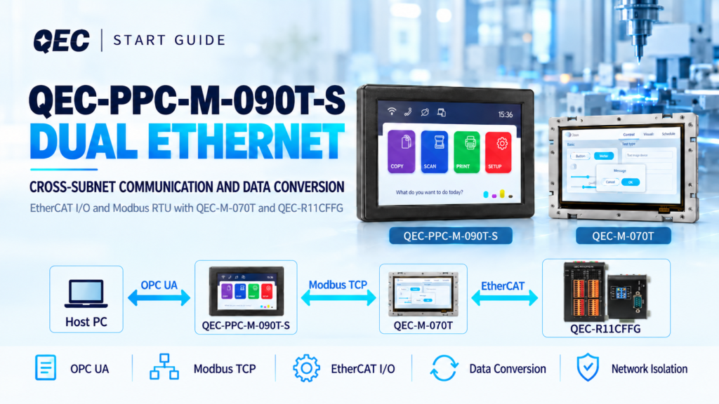
Key points of this article:
- Focus on the QEC-PPC-M-090T-S: its two Ethernet ports connect to the machine side and the host side separately, and the device converts data between the two.
- QEC runs and integrates multiple protocols at once: EtherCAT, Modbus RTU, Modbus TCP, and OPC UA are used in one system, and all data is displayed on the QEC panels.
- The EtherCAT-side configuration is only an example: the QEC-M-070T + QEC-R11CFFG + Modbus I/O board can be replaced with other EtherCAT devices or serial devices to suit your application. The QEC-PPC-M-090T-S implementation stays the same.
If you want to verify an OPC UA connection on a QEC on its own first, see [Test tool] QEC-M × OPC UA — Run Server and Client on the HMI. This article focuses on dual-Ethernet, cross-subnet data conversion; OPC UA is just one of the protocols the host side can use.
1. Overview: System Architecture and Device Roles
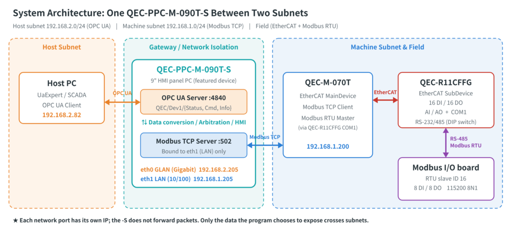
1.1 Device roles
| Device | Role | Communication |
|---|---|---|
| QEC-PPC-M-090T-S | Operator panel, protocol conversion, network isolation | LAN: Modbus TCP Server GLAN: OPC UA Server |
| QEC-M-070T | Field controller | EtherCAT MDevice, Modbus TCP Client, Modbus RTU Master |
| QEC-R11CFFG | EtherCAT I/O module | EtherCAT SubDevice; COM1 (RS-485) |
| Modbus I/O board | Field serial device (for demo) | Modbus RTU Slave (ID 16, 8 DI / 8 DO) |
| Host PC | Monitoring | OPC UA Client (UaExpert) |
1.2 GLAN and LAN responsibilities
| QEC-PPC-M-090T-S port | IP | Connected to | Purpose |
|---|---|---|---|
| GLAN | 192.168.2.205 | Host PC | Runs the OPC UA Server (:4840), provides data to the host system and receives commands |
| LAN | 192.168.1.205 | QEC-M-070T | Runs the Modbus TCP Server (:502), exchanges data with the field controller |
The two ports are on different subnets, so the host PC cannot connect to the QEC-M-070T directly. Only the data the program chooses to expose crosses between the subnets.
1.3 What you will verify
- DI states from the I/O board (via RS-485) are shown on the QEC-M-070T panel → COM-port Modbus RTU conversion works
- The same data is shown on the QEC-PPC-M-090T-S panel, and field outputs can be controlled from it → Cross-device communication on the LAN side works
- A host PC on another subnet can read data and send commands → Cross-subnet data conversion works
About the panel screenshots: The screenshots are generated directly from the example HMI projects. The ON / OFF state of each I/O point is for illustration only; your screens will differ depending on wiring and operation. Focus on the connection indicators and status text. Due to limited screen space, some panel labels use “-S” to mean QEC-PPC-M-090T-S, for example HOST ( -S ).
The screenshots were captured in sequence through Exercises A → B → C, so states carry over: QEC-R11CFFG DQ00 and I/O board DO0 (turned on in Exercise A) and I/O board DO3 (turned on in Exercise B) stay lit in later screenshots. The full-page screenshots in Sections 2 and 3 were taken after Step 1 of Exercise C (OPC WRITES switched to ACCEPT) and before any writes from UaExpert.
2. QEC-PPC-M-090T-S: Dual Ethernet and Data Conversion
2.1 Main: Status of all three services at a glance
The top of the QEC-PPC-M-090T-S Main page shows three cards for the machine-side, field-controller, and host-side connections. Below them is the field data reported by the QEC-M-070T.
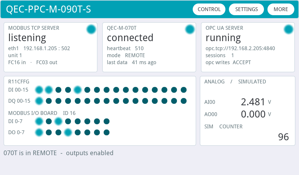
Figure 2: QEC-PPC-M-090T-S Main page
| Card | Indicator lit means | Status text |
|---|---|---|
| MODBUS TCP SERVER | The Modbus TCP Server on the LAN side is running | listening, eth1 192.168.1.205 : 502, unit 1 |
| QEC-M-070T | Up-to-date data has been received from the QEC-M-070T | connected, heartbeat (keeps increasing), mode LOCAL / REMOTE, last data N ms ago |
| OPC UA SERVER | The OPC UA Server on the GLAN side has started | running, opc.tcp://192.168.2.205:4840, sessions N, opc writes ACCEPT / IGNORE |
The status bar at the bottom summarizes the current state in one line, for example 070T is in REMOTE - outputs enabled in Figure 2.
2.2 How data crosses subnets
Acting as a Modbus TCP Client, the QEC-M-070T writes field data to the QEC-PPC-M-090T-S (Block A) and reads back commands (Block B) every 100 ms. The QEC-PPC-M-090T-S then maps the data in both blocks to OPC UA nodes for the host PC.
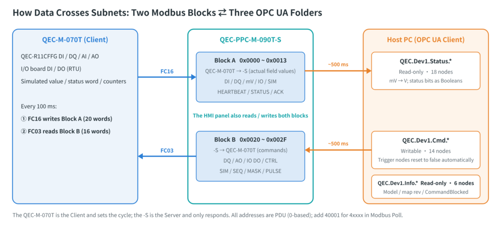
Figure 3: Mapping between Modbus Blocks A / B and OPC UA nodes.
| OPC UA folder | Access | Contents |
|---|---|---|
QEC.Dev1.Status | Read-only | Actual field state: DI / DO, analog values (converted to volts), simulated value, status word, and commonly used status bits |
QEC.Dev1.Cmd | Writable | Commands to the field: DQ / DO, AO, enable, pulse, reset, etc. |
QEC.Dev1.Info | Read-only | Model, register map version, connection diagnostics, and CommandBlocked (why a command has not taken effect) |
In the program, the Modbus TCP Server is bound to the LAN port when it is created:
mbBus.begin(MODBUS_TCP, 502, Ethernet1);   // Ethernet1 = LAN
mbNode.attach(1, mbBus);                   // unit ID 1
2.3 Conditions for commands to take effect
The QEC-M-070T panel, the QEC-PPC-M-090T-S panel, and the host PC can all control the same outputs. To prevent conflicts from multiple writers, the example uses clear conditions, visible on the panels, to manage control:
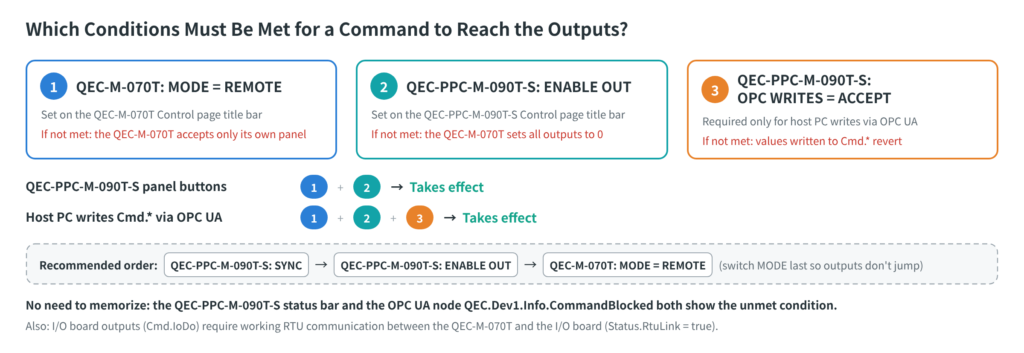
Figure 4: Conditions for commands to take effect.
| Condition | Where to set | If not met |
|---|---|---|
| ① QEC-M-070T MODE = REMOTE | QEC-M-070T Control page | The QEC-M-070T accepts only its own panel |
| ② ENABLE OUT | QEC-PPC-M-090T-S Control page | The QEC-M-070T holds all outputs at 0 |
| ③ OPC WRITES = ACCEPT (host PC only) | QEC-PPC-M-090T-S Control page | Values written by the host PC revert to their previous values |
When a command does not take effect, both the QEC-PPC-M-090T-S status bar and the OPC UA node QEC.Dev1.Info.CommandBlocked show which condition has not been met.
2.4 Detail: Connection quality and diagnostics
Tap MORE on the Main page to open the Detail page, which shows connection quality and communication counters.
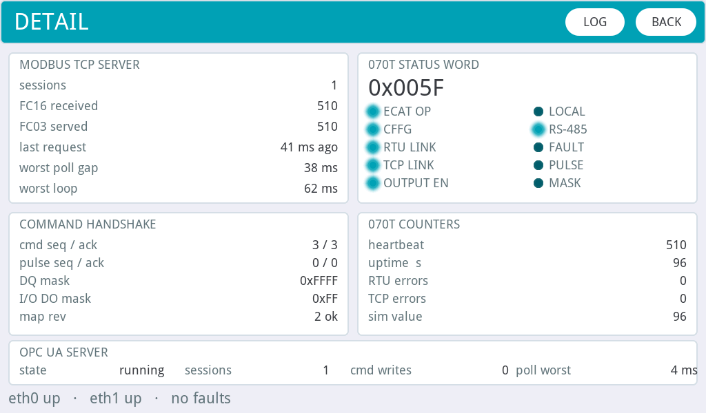
Figure 5: QEC-PPC-M-090T-S Detail page (same moment as Figure 2)
| Field | Normal value | Description |
|---|---|---|
sessions (MODBUS TCP SERVER) | Stays at 1 | A rising value means the connection keeps dropping and reconnecting |
worst poll gap | Tens of ms | Hundreds of ms or more means processing time is being taken by other tasks |
cmd seq / ack | The two values match | The QEC-M-070T has read the latest command |
map rev | 2 ok | MISMATCH means the two devices use different register map versions |
OPC UA SERVER state / sessions | running / 1 | sessions is 1 while UaExpert is connected |
| Bottom line | eth0 up · eth1 up · no faults | Status of both network interfaces |
3. QEC-M-070T + QEC-R11CFFG: EtherCAT I/O and Modbus RTU
3.1 The QEC-R11CFFG COM port can run Modbus RTU
Besides DI / DO / AI / AO, the QEC-R11CFFG has an RS-232 / RS-485 COM port. COM-port data travels over the same EtherCAT cable, so the QEC-M-070T can access field Modbus RTU devices without extra wiring or an RTU gateway.
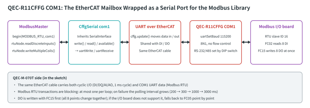
Figure 6: QEC-R11CFFG COM1 provides Modbus RTU communication over EtherCAT.
The example uses CffgSerial.h to wrap COM1 as a Serial interface, so the Modbus library can use it directly:
com1.init(&cffg, 0);                // QEC-R11CFFG COM1
com1.begin(115200);                 // 8N1
rtuBus.begin(MODBUS_RTU, com1);     // used just like a regular serial port
rtuNode.attach(16, rtuBus);         // I/O board slave ID 16
The QEC-M-070T reads the I/O board’s 8 DI with FC02 and writes all 8 DO at once with FC15, while running the QEC-R11CFFG EtherCAT I/O on a 1 ms cycle.
3.2 Main: Three field-side connections
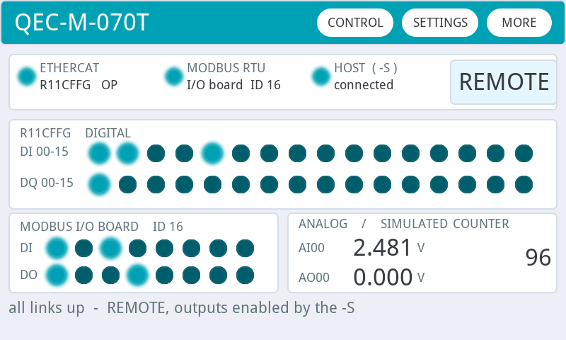
Figure 7: QEC-M-070T Main page
| Section | Indicator lit means |
|---|---|
| ETHERCAT | EtherCAT has reached OP (shows R11CFFG OP) |
| MODBUS RTU | RTU communication between COM1 and the I/O board is working (shows I/O board ID 16) |
| HOST ( -S ) | Connected to the QEC-PPC-M-090T-S via Modbus TCP (shows connected) |
| Top-right corner | Current mode: LOCAL (controlled from this panel, default at power-up) or REMOTE (accepts commands from the QEC-PPC-M-090T-S) |
3.3 Adapting the configuration to your application
The EtherCAT-side configuration in this example only serves to provide field data. Depending on your needs, you can:
- Use other EtherCAT devices, or add / remove I/O points and modules
- Replace the Modbus I/O board with another Modbus RTU device (the slave ID and baud rate can be changed on the QEC-M-070T SETTINGS page)
- Replace OPC UA with another host protocol (for example MQTT or a Web Server)
How the QEC-PPC-M-090T-S assigns a service to each of GLAN and LAN remains the same.
4. Preparation
4.1 Hardware
| Item | Qty |
|---|---|
| QEC-PPC-M-090T-S | 1 |
| QEC-M-070T | 1 |
| QEC-R11CFFG | 1 |
| Modbus RTU I/O board (8 DI / 8 DO, slave ID 16, 115200 bps 8N1, RS-485) | 1 |
4.2 Software
| Item | Description |
|---|---|
| 86Duino IDE 502 | Available from QEC Software Download (currently in beta). Version 501 does not include the OPC UA (open62541) library or the PPCM090 (None-EtherCAT) board option |
| open62541 library | In the IDE menu, go to Sketch → Include Library → Manage Libraries…, search for OPC, and install open62541 (used by the QEC-PPC-M-090T-S) |
| PL2303 driver | When a QEC is connected to the PC via USB Type-C, Device Manager should show Prolific PL2303GC USB Serial COM Port (COMx). If it does not, install the driver (Set up the QEC for 86Duino) |
| UaExpert | OPC UA Client installed on the host PC |
| Example programs | QEC-M-070T_demo (QEC-M-070T)QEC-PPC-M-090T-S_demo (QEC-PPC-M-090T-S)See Section 10 for download |
4.3 Wiring
| From | To | Purpose |
|---|---|---|
| QEC-PPC-M-090T-S GLAN port | Host PC | OPC UA (host subnet) |
| QEC-PPC-M-090T-S LAN port | QEC-M-070T Giga LAN port (blue) | Modbus TCP (machine subnet) |
| QEC-M-070T EtherCAT port (EC IN / EC OUT) | QEC-R11CFFG | EtherCAT |
| QEC-R11CFFG COM1 | Modbus I/O board | RS-485 (A to A, B to B, common GND); set the QEC-R11CFFG DIP switch to RS-485 |
Tip: The two 10/100 Mbps ports on the QEC-M-070T are for EtherCAT only. Be sure to connect the QEC-PPC-M-090T-S to the blue Giga LAN port.
4.4 Network settings
The example programs use the following factory defaults. If your subnets are the same, no changes are needed:
| Device | IP | Mask | Gateway |
|---|---|---|---|
| Host PC | 192.168.2.82 | 255.255.255.0 | Leave blank |
| QEC-PPC-M-090T-S GLAN | 192.168.2.205 | 255.255.255.0 | 192.168.2.1 |
| QEC-PPC-M-090T-S LAN | 192.168.1.205 | 255.255.255.0 | 192.168.1.1 |
| QEC-M-070T | 192.168.1.200 | 255.255.255.0 | 192.168.1.1 |
Caution: Do not set a gateway on the host PC network adapter connected to GLAN, or it may override the PC’s existing default route.
To change a QEC IP address, edit it on the device’s SETTINGS page, tap CONFIRM to save, and restart the device for the change to take effect.
5. Uploading the Programs
Upload each device separately. We recommend connecting only one device via USB at a time to avoid selecting the wrong port.
- Connect the QEC’s USB Type-C port to the PC with a USB Type-C cable, and power on the QEC.
- Open the example sketch in 86Duino IDE 502.
- Click the 86HMI button in the IDE to open 86HMI Editor. Make sure the loaded project is
data/_project.hpjinside the sketch folder, then click Code Generation to generatemyhmi.h/myhmi.cpp. - Select the model under Tools → Board, and the device’s COM port under Tools → Port (shown as
COMx (QEC)):
| Device | Sketch | Board |
|---|---|---|
| QEC-M-070T | QEC-M-070T_demo.ino | QEC M070T |
| QEC-PPC-M-090T-S | QEC-PPC-M-090T-S_demo.ino | PPCM090 (None-EtherCAT) |
- Click ✓ on the toolbar to compile. If there are no errors, click → to upload.
Tip: For the QEC-PPC-M-090T-S, do not select QEC PPCM090 (that option is for the EtherCAT version). If the wrong board is selected, compilation fails with Select Tools > Board > "PPCM090 (None-EtherCAT)" ….
6. Exercise A: Standalone Test of the QEC-M-070T
In this step, only the QEC-M-070T is powered on, to confirm that EtherCAT I/O and COM-port Modbus RTU are working.
- Power on the QEC-M-070T and check the Main page:
- The ETHERCAT indicator is lit and shows
R11CFFG OP - The MODBUS RTU indicator is lit and shows
I/O board ID 16 - The HOST ( -S ) indicator is off and shows
unreachable: this is normal, as the QEC-PPC-M-090T-S is not connected yet - The top-right corner shows
LOCAL
- The ETHERCAT indicator is lit and shows
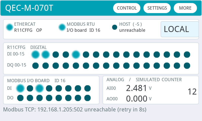
Figure 8: Main page with only the QEC-M-070T powered on
- Apply a signal to a DI terminal on the QEC-R11CFFG or I/O board. The corresponding DI indicator on the Main page should light up.
- Tap CONTROL to open the Control page, enter
5in the AO field, and tap SET. AO00 should output 5 V. - Tap ALL ON. All 16 DQ on the QEC-R11CFFG and all 8 DO on the I/O board should turn on together. Then tap ALL OFF to turn off all outputs (AO00 also returns to 0 V).
- Tap DQ
00and DO0. QEC-R11CFFG DQ00 and I/O board DO0 turn on, and the status bar showsI/O board DO0 = 1. Leave these two outputs on; you will check them in Exercise B.
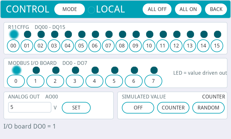
Figure 9: Control page after Step 5.
Tip: If the MODBUS RTU indicator is not lit, check whether RS-485 A / B are swapped, whether the DIP switch is set to RS-485, and the I/O board’s slave ID and baud rate. If the I/O board is not slave ID 16 / 115200 bps, change BAUD and SLAVE in the COM1 section of the SETTINGS page, tap CONFIRM, then tap RECONNECT.
7. Exercise B: Controlling Field I/O from the QEC-PPC-M-090T-S (LAN)
7.1 Connect and check the data
- Connect the QEC-PPC-M-090T-S LAN port to the QEC-M-070T Giga LAN port with an Ethernet cable, and power on the QEC-PPC-M-090T-S. The QEC-M-070T reconnects automatically (retry interval up to 15 seconds).
- Check the QEC-PPC-M-090T-S Main page:
- MODBUS TCP SERVER: indicator lit, shows
listening - QEC-M-070T: indicator lit, shows
connected,heartbeatkeeps increasing,mode LOCAL - The field data below matches the QEC-M-070T panel (the lit DQ00 and DO0 in Figure 10 are the two outputs turned on in Exercise A)
- MODBUS TCP SERVER: indicator lit, shows
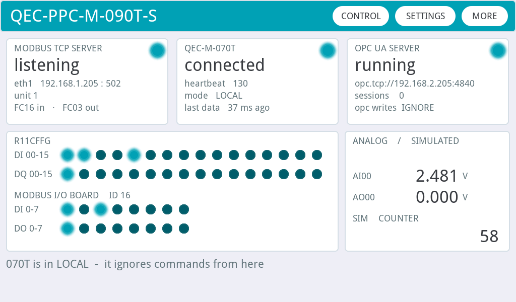
Figure 10: QEC-PPC-M-090T-S Main page after connecting, with the QEC-M-070T still in LOCAL.
7.2 Send commands
- On the QEC-PPC-M-090T-S, tap CONTROL, then tap SYNC to copy the QEC-M-070T’s current actual outputs into this panel’s command values.
- Tap ENABLE OUT to allow the QEC-M-070T to drive its outputs.
- On the QEC-M-070T Control page, tap MODE to switch to
REMOTE. Because SYNC and ENABLE OUT were done first, the existing outputs (DQ00, DO0) stay unchanged during the switch. - Back on the QEC-PPC-M-090T-S, tap any DQ / DO button. The corresponding field output switches, and the indicator above the button lights up. In this example, tap DO
3of the I/O board.
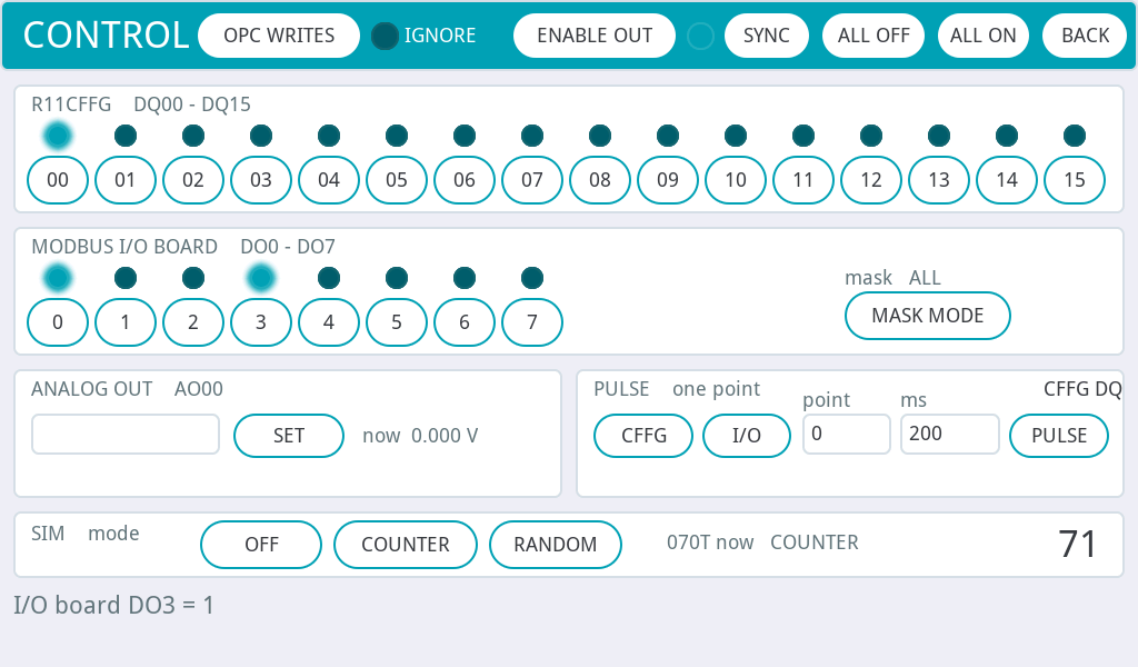
Figure 11: After SYNC, ENABLE OUT, switching the QEC-M-070T to REMOTE, and then tapping DO 3.
Caution: Follow the order above. If you switch the QEC-M-070T to REMOTE before pressing ENABLE OUT, the QEC-M-070T resets all outputs to 0 at the moment of switching, and SYNC will then only copy all-zero values. After SYNC, do not change outputs on the QEC-M-070T panel.
You can also try ALL ON / ALL OFF, PULSE (select I/O, point 0, ms 500), and AO SET.
8. Exercise C: Accessing Data from the Host PC with UaExpert (GLAN)
8.1 Connect and read
- Connect the host PC to the QEC-PPC-M-090T-S GLAN port, set the PC’s IP to
192.168.2.82(leave the gateway blank), and confirm the connection withping 192.168.2.205. - Check that the OPC UA SERVER card on the QEC-PPC-M-090T-S Main page shows
runningandopc.tcp://192.168.2.205:4840. - In UaExpert, choose Add Server, enter
opc.tcp://192.168.2.205:4840, select None for Security Policy, and connect. - Expand
Objects > QEC > Dev1and drag the nodes underStatusinto the Data Access View:Status.SimValuekeeps changing → data is flowing (a simulated value built into the QEC-M-070T, incrementing by 1 every second by default)Status.IoDiis the I/O board DI received via RS-485Status.CffgAiis already converted to volts (V)
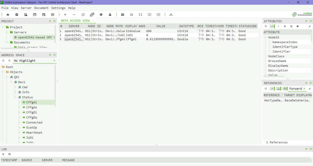
Figure 12: UaExpert address space and Data Access View. Status.SimValue, Status.IoDi, and Status.CffgAi (in volts) can be read directly.
The host PC is on the 192.168.2.x subnet and cannot connect directly to the QEC-M-070T on 192.168.1.x, yet it can still get all of its I/O data. This is the result of the QEC-PPC-M-090T-S converting data between GLAN and LAN.
8.2 Send commands
- On the QEC-PPC-M-090T-S Control page, tap OPC WRITES. The text next to it changes from
IGNOREtoACCEPT(REMOTE and ENABLE OUT from Exercise B must remain in place). - Write the following nodes in UaExpert:
| Purpose | Node | Value |
|---|---|---|
| All 8 I/O board outputs on / off | QEC.Dev1.Cmd.IoDo | 255 / 0 |
| Turn on only QEC-R11CFFG DQ00 | QEC.Dev1.Cmd.CffgDq | 1 |
| AO output 5 V | QEC.Dev1.Cmd.CffgAo | 5.0 |
| 0.5-second pulse on I/O board DO0 | Write in order: Cmd.PulseTarget = 2,Cmd.PulsePoint = 0, Cmd.PulseMs = 500,then write Cmd.PulseTrigger = true |
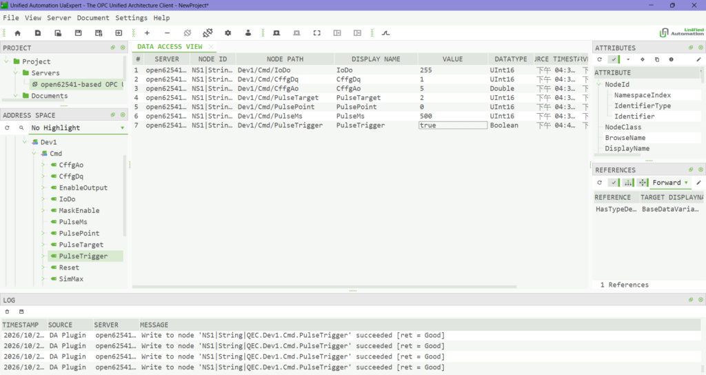
Figure 13: Writing Cmd.* nodes in the Data Access View; the Log below shows the writes succeeded.
- Within about 0.5 seconds of writing, the field outputs switch, and
Status.*and the QEC-PPC-M-090T-S panel indicators update accordingly.
Tip: If a command does not take effect, read QEC.Dev1.Info.CommandBlocked; it states which condition is not met (an empty string means all conditions are met). If a written value reverts to its previous value, OPC WRITES is still set to IGNORE.
9. Troubleshooting
| Symptom | Check first | Possible cause |
|---|---|---|
| QEC-M-070T ETHERCAT indicator not lit | QEC-M-070T Main page status bar | QEC-R11CFFG not powered, or cable not connected to the EtherCAT port |
| QEC-M-070T MODBUS RTU indicator not lit | Bottom line of the QEC-M-070T Detail page | RS-485 A / B swapped, DIP switch not set to RS-485, or mismatched slave ID or baud rate |
Second card on the QEC-PPC-M-090T-S shows no data | LAN cable, IP of both devices | QEC-M-070T not connected; make sure it is on the Giga LAN port and that PORT (502) and UNIT (1) match |
| Output buttons have no effect | QEC-PPC-M-090T-S status bar | A condition is not met; the status bar shows which one |
| UaExpert cannot connect | PC IP and gateway | The PC must be on 192.168.2.x with no gateway; ping 192.168.2.205 first |
| Values written in UaExpert revert | QEC-PPC-M-090T-S OPC WRITES | Still set to IGNORE; switch it to ACCEPT |
map rev on the Detail page shows MISMATCH | Program version on both devices | Both devices must run the same version of the example programs |
10. Resources
- Start Guide (PDF): QEC-PPC-M-090T-S_StartGuide_EN | QEC-PPC-M-090T-S_StartGuide_zh-TW
- Example program (ZIP): QEC-PPC-M-090T-S_demo | QEC-M-070T_demo
- 86Duino IDE 502 and QEC software tools: Software
We will continue to deliver robust and innovative EtherCAT automation platforms that make machine integration smarter and faster. For any questions or requests, please contact us at info@qec.tw.