Two OPC UA test tools that run on any QEC-M-series MDevice with a built-in panel — one is the server, the other is the client — putting both ends of an OPC UA link on the panel. The server sketch is online at boot, so UaExpert on a PC, or the plant SCADA or MES, connects the standard way and reads and writes data. The client sketch goes the other way: type a target endpoint on the panel, press CONNECT, and walk the other end’s address space, read and write values, subscribe to nodes.
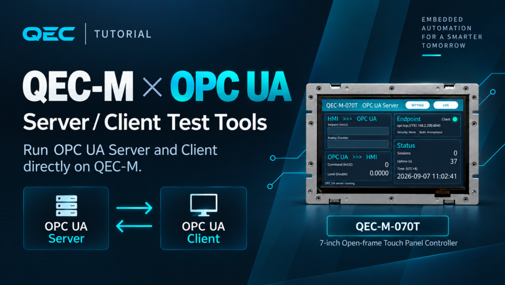
Neither side needs a PC. No external gateway, no laptop parked next to the machine, no separate HMI host. For machine builders and system integrators bringing up OPC UA: spend ten minutes proving the QEC speaks OPC UA, and the rest is wiring it into your own system.
1. Two Sketches, Both Ends of One Link
An OPC UA connection is always client-initiated and server-passive; two clients cannot talk to each other. So the first thing to settle before you start is: which role does this QEC play in your system?
| QEC_OPCUA_Server_HMI | QEC_OPCUA_CLIENT_HMI | |
| Role | Waits passively to be connected to | Connects out, and never on its own at boot |
| Who connects to whom | SCADA / MES / UaExpert connects into the QEC | The QEC connects into a third-party PLC, a demo server, or another QEC |
| Panel pages | Three: Main / Log / Settings | Five: Home / Browse / Node / Log / Setup |
| Network defaults | Itself at 192.168.2.200, port 4840 | Itself at 192.168.1.200, target 192.168.1.100:48010 |
| What you can see | Its own ten published nodes, and how many clients are attached | Everything in the other end’s address space — node tree, types, access rights, live values |
| Typical use | Prove the QEC’s data reaches the upstream system | Prove the QEC can reach the other end, and find out what it has |
Which one should I start with? If your goal is “the upstream system can read the QEC’s data”, read §2 and §4. If it is “the QEC reads someone else’s data”, read §3 and §5. If you need both, do the server run first — it needs only one QEC and a PC, so there are fewer variables.
2. The QEC as a Server: Publishing Data
- Online at boot —
setup()applies the static IP stored in EEPROM, builds theObjects/QECnode tree and starts listening on the configured port.OPC UA server runningappears on serial and on the panel Log at the same time. - Data flows both ways —
Setpoint/Analogare entered on the panel and read upstream;Command/Levelare written upstream and appear on the panel within 200 ms. - Connection state is visible — the
ClientLED and theSessionscount show how many clients are attached right now. - Changing the network needs no reflash — IP / subnet / gateway / port are entered on the Settings page, stored in EEPROM, and applied by pressing REBOOT on the panel.
- “Saved” and “in effect” stay distinguishable — the
Active nowcolumn on the Settings page always shows what is actually running; two columns that differ mean the device has not been restarted yet.
2.1 Main — Both Directions at a Glance
The left half is the two directions of data flow, the right half is connection information. Tap a field for the touch keypad, confirm, and the value is written to the node immediately; the status bar at the bottom reads HMI -> Setpoint = 55. Values written from upstream appear on the panel within 200 ms, with OPC UA -> Command = 77 on the status bar.
The Endpoint line is filled in at boot with the IP and port actually in effect, not a hard-coded string — you can copy it straight into UaExpert.
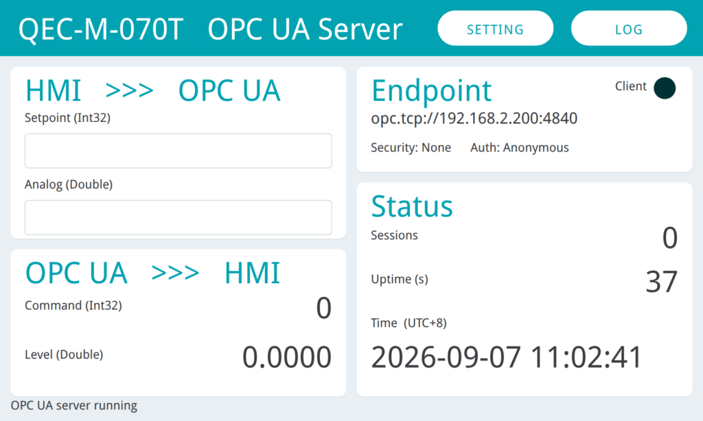
Figure 2-1 — Idle (LED dim, Sessions = 0)
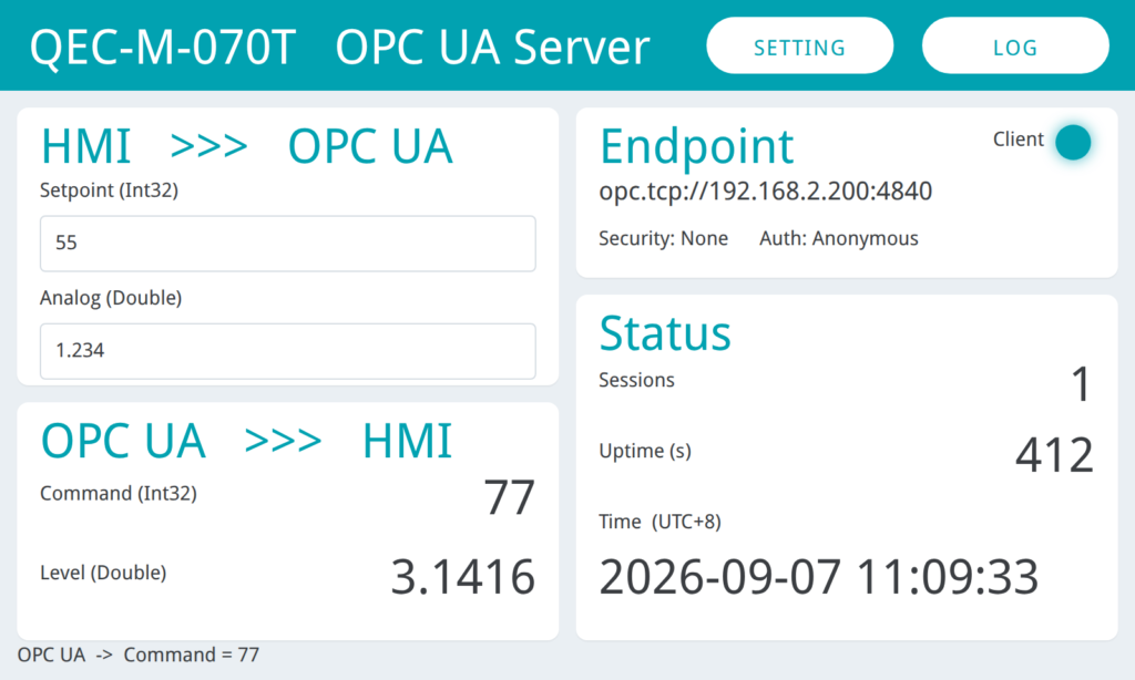
Figure 2-2 — connected (LED lit, Sessions = 1, all four nodes carrying values).
2.2 Log — a Live Console on the Panel
99 numbered lines, auto-scrolled to the newest entry, every line stamped with local time, and matching the serial monitor (115200) — except the two boot lines, which are serial-only. When it fills up it is cleared with ----- log full - cleared and restarted ----- on line 1, so you are never left with a handful of lines and no idea that a wrap happened.
When the panel is all you have on site, this page is your only debug window.
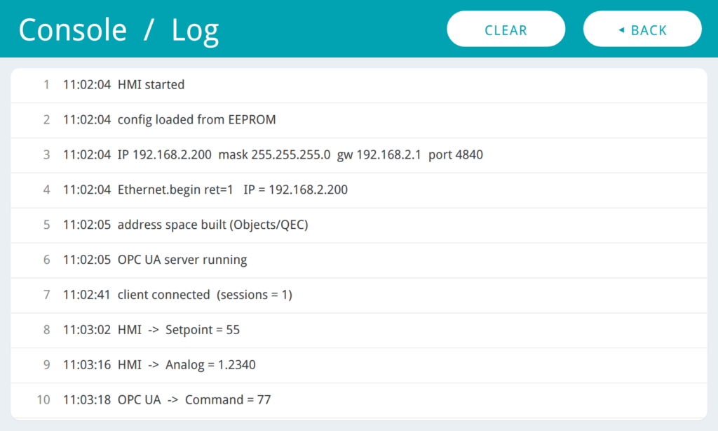
Figure 2-3 — The Log page with the boot sequence plus client connected (sessions = 1).
2.3 Settings — Change IP or Port Without Reflashing
The left column holds the values stored in EEPROM and applied at the next boot; the right column, Active now, is what is actually running. Two columns that differ mean settings were changed but the device has not been restarted — no need to jump back to the main page and compare the endpoint. Every time you enter this page the left column is refilled from the stored settings, so an edit you never CONFIRMed does not linger.
CONFIRM validates before writing, and if any check fails it shows the reason and writes nothing: format, port range, the mask must be contiguous (255.0.255.0 is rejected — saved and restarted, it would take the whole device off the network), and the IP must not be the network or broadcast address of its subnet. A gateway outside the subnet warns but does not block.
DEFAULT is the way back when an address is wrong, the unit is unreachable and you would rather not reflash;
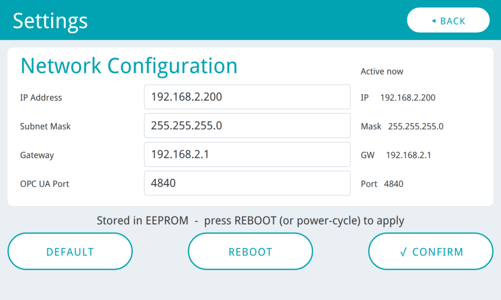
Figure 2-4 — Both columns match on entry
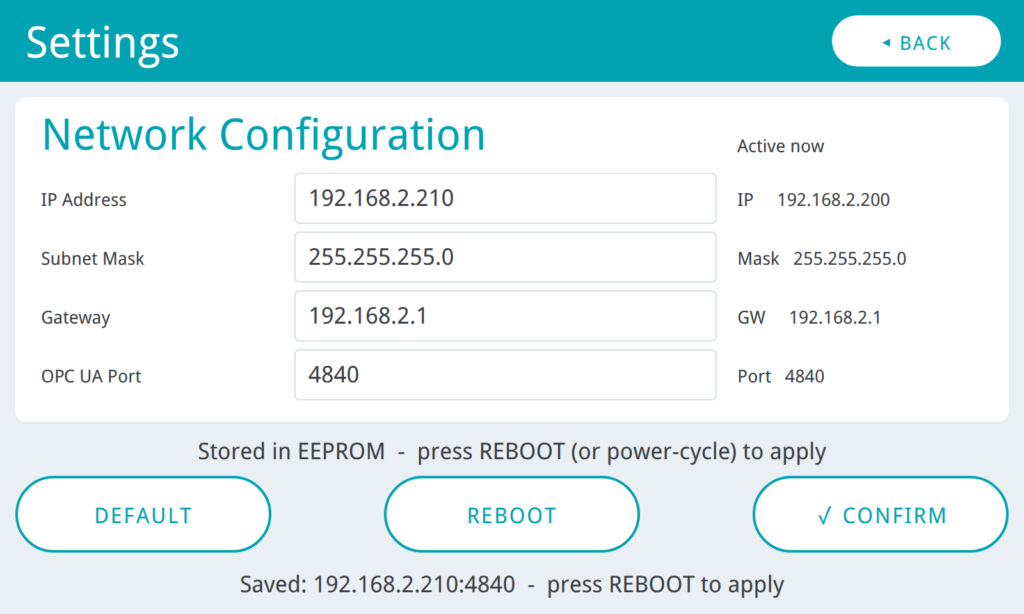
Figure 2-5 — a new IP in the left column while Active now still shows the old value (= not applied yet).
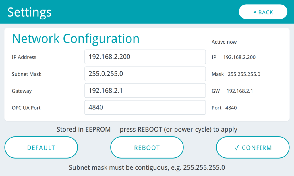
Figure 2-6 — 255.0.255.0 entered as the subnet and rejected.
REBOOT lets “save → take effect” be completed on the panel. Both need two presses within 3 s so they cannot be hit by accident.
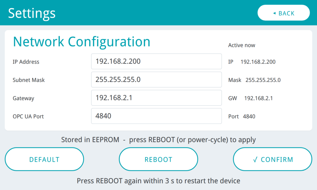
Figure 2-7 — After one press of REBOOT, the status bar reads Press REBOOT again within 3 s to restart the device.
2.4 Address Space — a Ten-Node Contract
| Objects/QEC | DataType | Direction | Note |
|---|---|---|---|
| Setpoint | Int32 | RO | <- panel out, read-only to clients |
| Analog | Double | RO | <- panel out, read-only to clients |
| Command | Int32 | RW | <- written by the client |
| Level | Double | RW | <- written by the client |
| Counter | Int32 | RO | <- increments every second; subscribe to watch it publish |
| Uptime | Int32 | RO | |
| Sessions | Int32 | RO | |
| ModelName | String | RO | |
| SketchVersion | String | RO | |
| IpAddress | String | RO |
Every node sets its dataType explicitly, so UaExpert’s DataType column reads Int32 / Double / String instead of a vague BaseDataType — your upstream system never has to guess.
Direction is part of the contract too: Setpoint / Analog are read-only to clients (the panel is their only source), while Command and Level are the ones clients write. Writing in the wrong direction returns BadNotWritable outright, rather than appearing to succeed while the panel ignores it.
Adding a node of your own is one line in buildAddressSpace():
addVar("QEC.MyValue", "MyValue", &UA_TYPES[UA_TYPES_FLOAT], &f0, RW);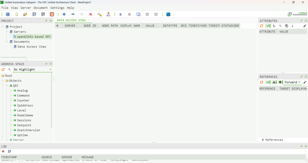
Figure 2-8 — UaExpert’s Address Space with all ten nodes under Objects/QEC expanded.
2.5 Connection Indicator and Session Count
The LED to the right of Endpoint on the Main page is lit while a client is connected and dim when none is; Sessions shows the current session count. The moment a client connects or disconnects, the status bar and the Log show:
client connected  (sessions = 1)
client disconnected  (sessions = 0)
This turns out to be genuinely useful on site: whether the panel lights up is the answer to “has the upstream system actually connected?” — no need to go back and check the SCADA’s connection list.
3. The QEC as a Client: Browsing Any Server from the Panel
- The panel never freezes — when the other end is unreachable,
UA_Client_connect()burns its whole timeout, which means every retry kills the screen. This tool usesconnectAsync()instead and advances the handshake by 20 ms per pass ofloop(), so you can still change pages while it is retrying an address that does not answer. - Browse the address space on the panel — ten rows per page, drill into folders and walk back out. Finding out what a server publishes takes no PC-side client.
- The values are already in the list — one batched Read fills the whole page in a single round trip, so you see ten live values without opening a single node.
- The input widget follows the DataType — numeric and boolean get the numeric keypad, strings the full keyboard, based on the node’s own declared DataType rather than a guess from the value.
- Six favourites survive a power cycle — save the nodes you keep coming back to; they live in EEPROM alongside the target URL and the subscription intervals.
3.1 Home — the Connection, and Nothing Else
The endpoint field sits on this page rather than in a settings screen, because pointing the tool at a different server is the single most common thing you will do. APPLY validates and stores it — and if a session is already up, reconnects to the new address in one step.
channel= and session= are the raw OPC UA state machine, not a simplified “connected” flag: when something goes wrong, they tell you how far the handshake got. The Session LED is the one-glance answer to “am I actually connected?”.
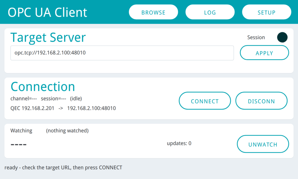
Figure 3-2 — At boot (nothing connected, LED dimmed, waiting for CONNECT)
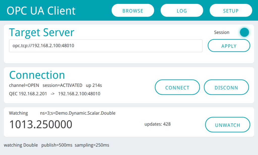
Figure 3-3 — a live session (LED fully lit, channel OPEN / session ACTIVATED, one node being watched).
It does not connect out by itself at boot. A test tool faces a different server every time, so redialling the last address is of little value — and stalling in the first few seconds after power-on is the worst possible first impression. Retries start only after CONNECT has been pressed, with a 1 → 2 → 5 → 10 s backoff, so the log is never flooded.
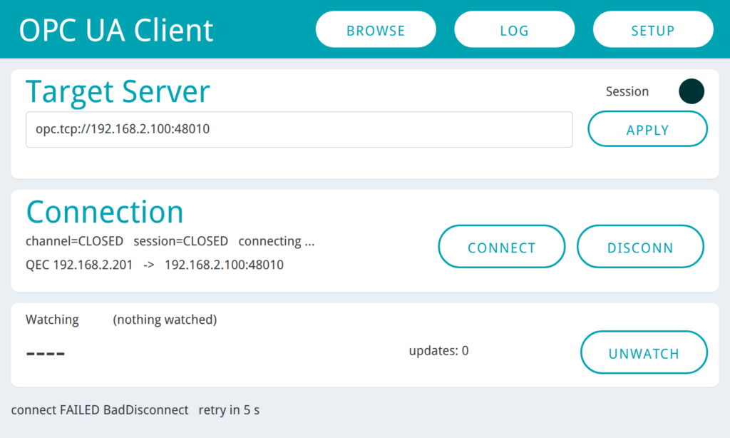
Figure 3-4 — A failed attempt: the reason and the retry countdown share one status bar, and the panel stays fully usable throughout .
3.2 Browse — Find the Node Without a PC
Ten rows per page. The left column tells you what each row does: > drills down, < is .. up one level, blank is a leaf. The breadcrumb shows the last two path levels and the page number.
What makes this page worth using is the right column. After every browse and on every page turn, the tool collects the ReadValueId of every Variable on the current page and sends them in one Read service call — one round trip per page, not one per node. Ten live values, with nothing opened.
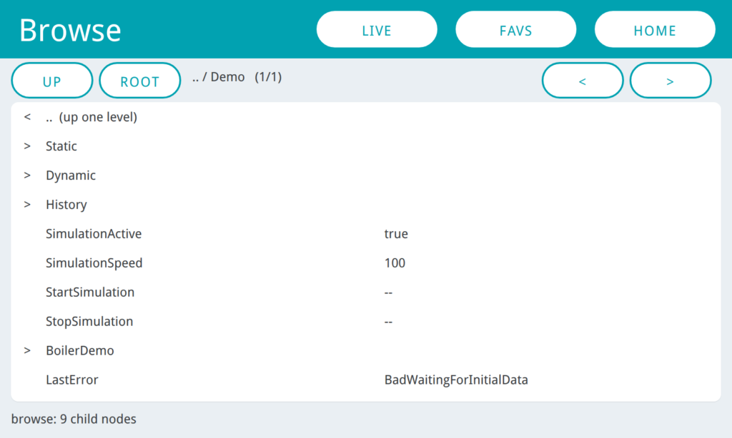
Figure 3-5 — One level inside Demo (folders marked >, no value shown),
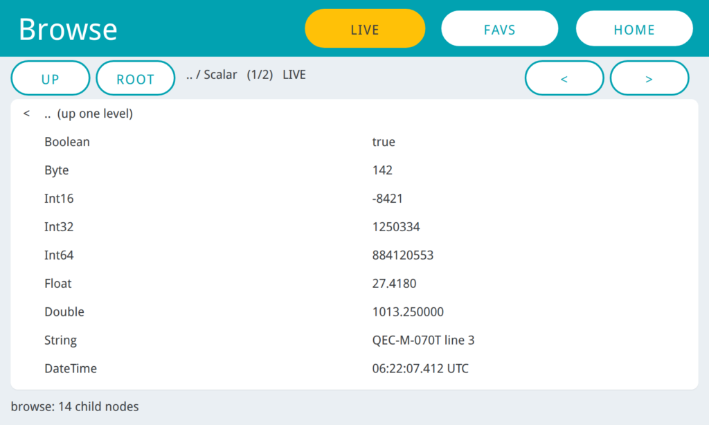
Figure 3-6 — and the same page with LIVE on — the button turns amber, the breadcrumb carries a LIVE marker, and the whole page is re-read every second.
LIVE is off by default; leaving the page pauses the refresh and coming back resumes it.
FAVS swaps the list for the six stored favourites — BrowseName on the left, the full NodeId on the right. FAV on the Node page is a toggle: it saves, or removes if already saved. When all six slots are taken the tool refuses rather than silently overwriting one.
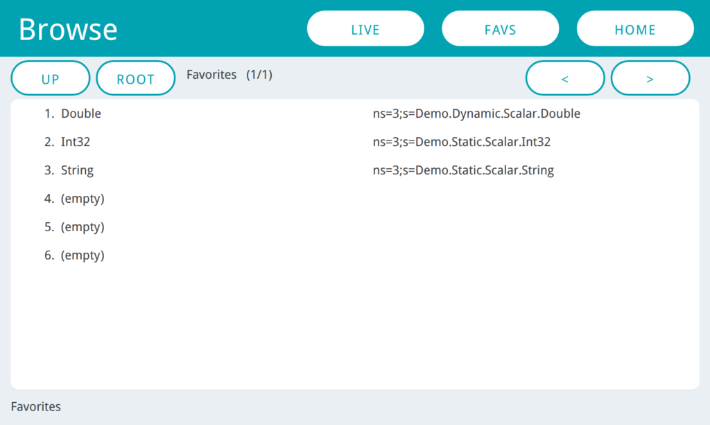
Figure 3-7 — The six favourite slots. Tapping a row opens that node directly, with no browsing.
3.3 Node — Read It, Write It, Watch It
Opening a node reads four attributes plus the value: NodeClass, BrowseName, DataType, AccessLevel, and the value with both timestamps. Access is shown before you try to write, so a BadNotWritable is never a surprise.
Reading the DataType attribute — rather than inferring the type from a value that came back — is what lets the tool write to a node it has never read, and it is what picks the input widget:
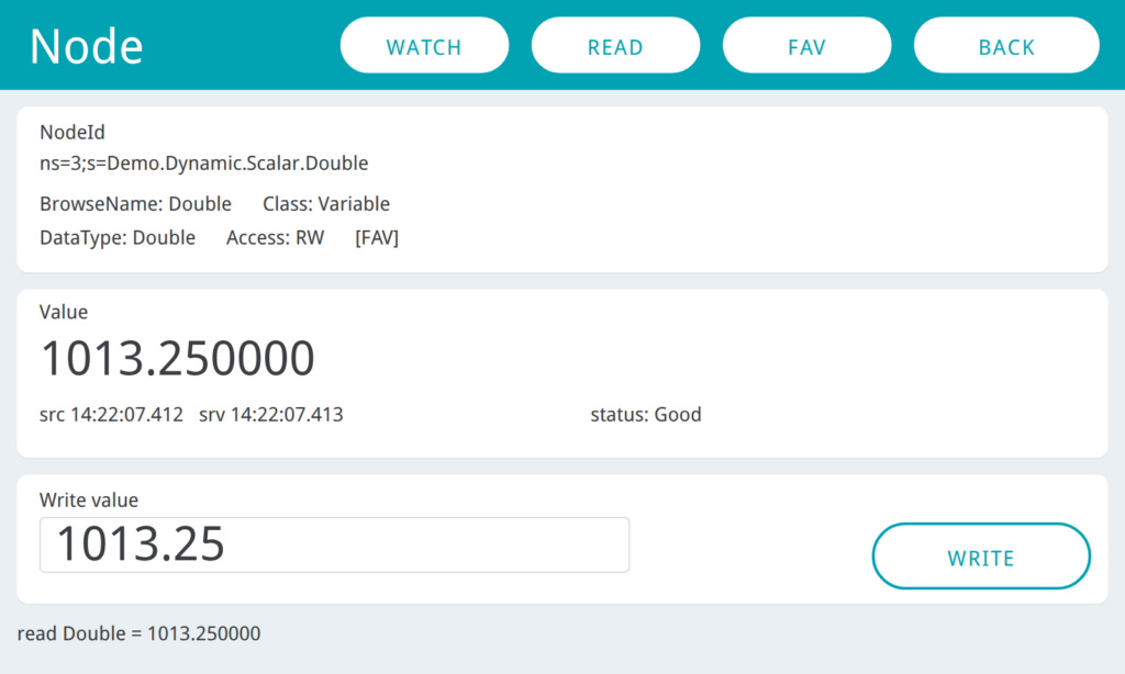
Figure 3-8 — A Double node (NumberInput, numeric keypad)
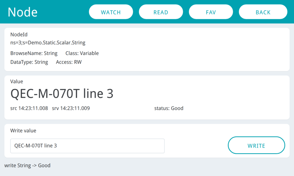
Figure 3-9 — A String node (TextInput, full keyboard).
WATCH subscribes to the node — one at a time, with the publishing and sampling intervals from the Setup page. The intervals the server actually granted come back in the status bar (watching Double publish=500ms sampling=250ms), which is often not what you asked for. The watched value then lives on the Home page with a rising updates: count, so you can leave it running while you browse elsewhere.
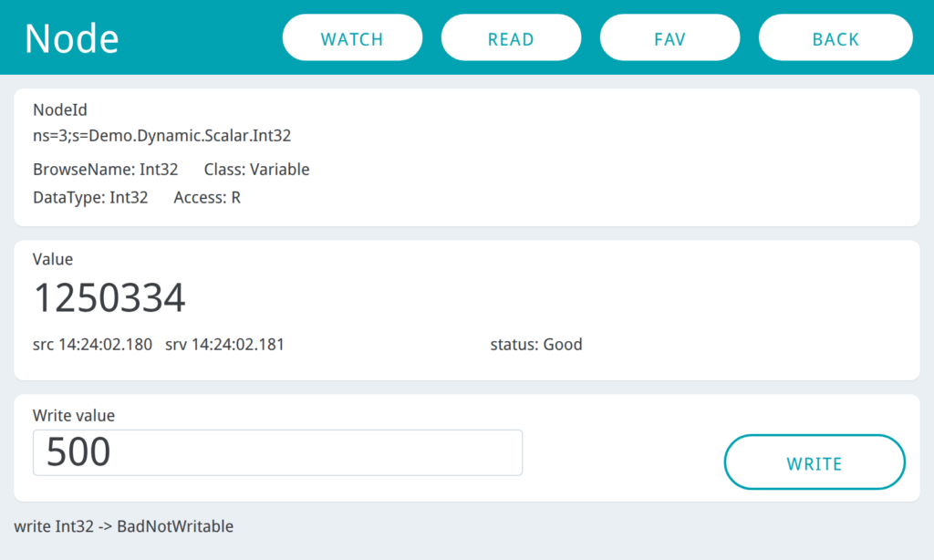
Figure 3-10 — Writing a node whose AccessLevel is R: the server answers BadNotWritable and the status bar says so.
3.4 The One Hard Constraint — the Endpoint Host Must Be an IP
opc.tcp://192.168.2.100:48010     works
opc.tcp://MYPC:48010              rejected before it is even stored
SIPtoNIP() in the 86Duino port of open62541.c replaces getaddrinfo(), because DJGPP has no netdb.h. Rather than let a host name fail later with an error that gives no clue why, urlProblem() rejects it at entry time: URL host must be an IP address, not a hostname.
A host name inside the endpoint the server reports back is fine — the open62541 1.1 client neither compares nor redials the endpoint URL. So a server that advertises itself as opc.tcp://SOMEPC:48010 still works; you just type its IP instead.
3.5 Log — the Same Console, Three Status Bars
The same as on the server sketch: 99 numbered lines, auto-scrolled, matching the serial monitor. The difference here is that Home, Browse and Node each carry a status bar, and setStatus() writes all three at once — so whichever page you are on shows the result of the last action.
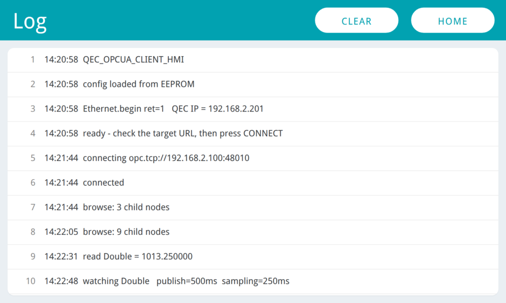
Figure 3-11 — Boot, connect, browse, read, watch and a rejected write, all timestamped.
4. Walkthrough A: The Server with UaExpert
The steps below use UaExpert on a PC (Unified Automation’s free OPC UA client) as the upstream system, and walk the shortest path: connect → see the nodes → write one value in each direction. About ten minutes, with no code to write.
UaExpert is simply the most convenient stand-in. An existing SCADA or MES, or a client you wrote yourself with Python
opcuaor the C# OPC Foundation SDK, connects just as well — it makes no difference to the QEC; the endpoint and node names are identical.
- Put the cable in the Gigabit RJ45 port (the two 10/100 ports are EtherCAT-only and will not carry OPC UA)
- IDE →
Sketch→Include Library→Manage Libraries...→ searchOPC→ install open62541 - Check that
DEF_IP/DEF_MASK/DEF_GW/DEF_PORTat the top ofQEC_OPCUA_Server_HMI.inomatch your subnet - Select your QEC-M model as the board (QEC-M-070T here) → Upload; the serial monitor (115200) shows
OPC UA server running
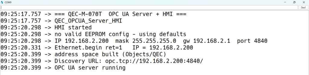
Figure 4-1 — Step 4: you need Ethernet.begin ret=1, a Discovery URL: that is an IP, and OPC UA server running as the last line.
- Confirm the
Discovery URL:line on serial is an IP (not86Duino) and note the endpoint - Install UaExpert; the first launch creates an Application Instance Certificate
Server→Add...→ expand Custom Discovery → double-click< Double click to Add Server... >→ enteropc.tcp://192.168.2.200:4840→ expand that row with its>and selectNone - None (uatcp-uasc-uabinary)underneath → set Authentication to Anonymous → OK
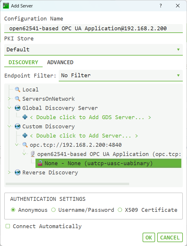
Figure 4-2 — Step 7 adding the server (expand the endpoint, pick None - None)
Step 7 is where people get stuck: with only the URL row selected, the
OKbutton stays greyed out — you have to expand it and pickNone - None (uatcp-uasc-uabinary)underneath. And aLocal Networkscan will never find this unit (the Discovery service is not compiled in), so the URL always has to be typed in by hand.
- Right-click the server → Connect; the panel LED lights and
Sessionsgoes to 1
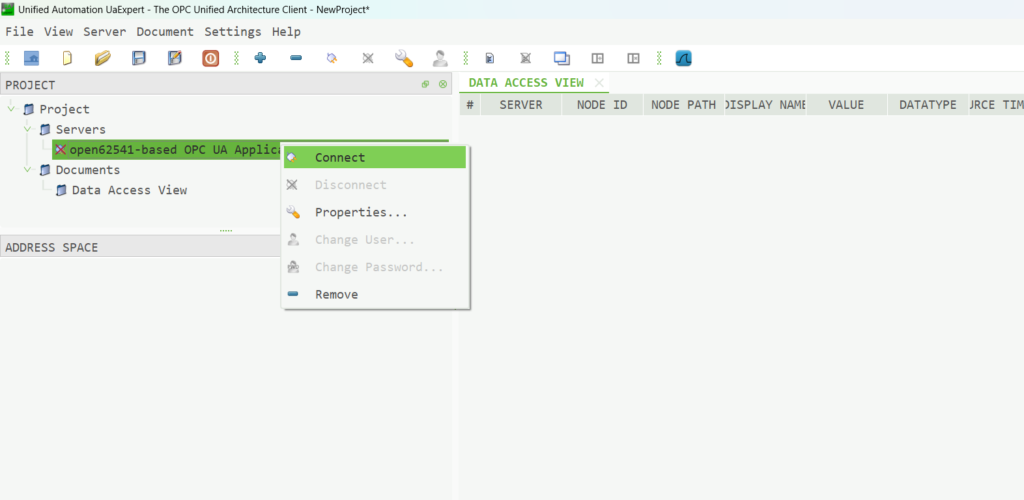
Figure 4-3 — Step 8 right-click Connect
- Expand
Root / Objects / QECin the address space, drag nodes into the Data Access View, enterSetpoint = 55on the panel and writeCommand = 77from UaExpert — confirm both directions
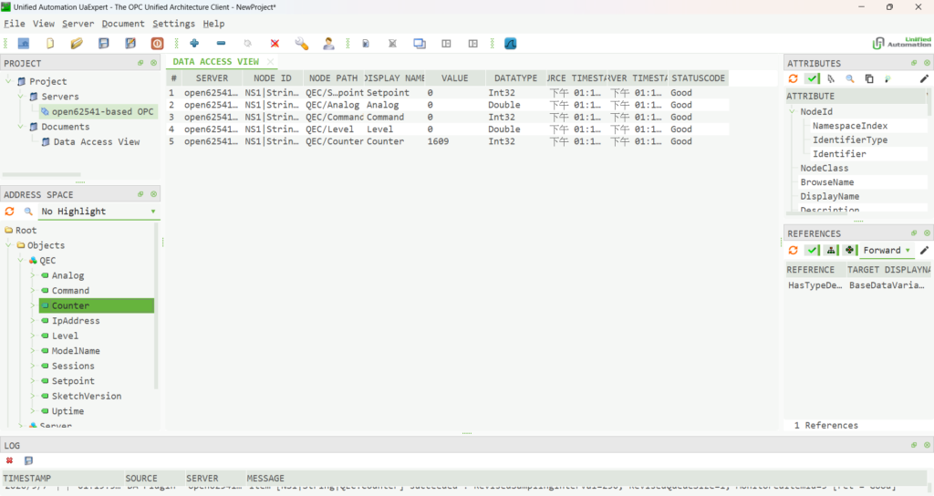
Figure 4-4 — Step 9 dragging nodes into the Data Access View.
One run through confirms three things: the QEC is discoverable on your network as a standard OPC UA server, the data types it publishes are correct, and data moves in both directions.
Two things are worth noticing along the way: drag Counter into the DA View and it increments every second with the timestamp following it (subscription publishing works, which is also the prerequisite for running EtherCAT alongside later); and writing to the read-only Setpoint returns BadNotWritable outright (direction protection working, and expected).
5. Walkthrough B: The Client Against Any Server
This run goes the other way, with the QEC connecting out. It uses Unified Automation’s demo server (UaCPPServer) as the target, but any OPC UA server will do — see the table below.
- The cable goes in the Gigabit RJ45 port again
- Select your QEC-M model as the board → upload
QEC_OPCUA_CLIENT_HMI; the serial monitor ends withready - check the target URL, then press CONNECT

Figure 5-1 — Step 2: the two lines that matter are Ethernet.begin ret=1 (a 0 means networking did not start) and QEC IP = showing the configured address rather than 0.0.0.0. It does not connect out by itself; the last line is asking you to press CONNECT.
- On the panel,
SETUP→ confirmActive nowmatches your subnet →BACK - Tap the
Target Serverfield, enteropc.tcp://<server IP>:48010, confirm, press APPLY - Press CONNECT; the
SessionLED lights and the line readschannel=OPEN session=ACTIVATED - Press
BROWSE— the list already showsObjects, browsed automatically on connect. Tap a>row to drill in - Find a folder of Variables and press LIVE; open a node, press
READ, write a value, thenWATCHit and go back toHOMEto see the updates arrive
Two checks matter most. Walk into a folder of Variables and confirm the values are already there without opening a node, which proves the batched read. And open a String node and confirm the write field became a text box with the full keyboard, which proves the write path follows the node’s declared DataType.
5.1 Any OPC UA Server Will Do
Nothing in this tool is specific to the demo server. If a server is already on the network, point the QEC at it and skip the install entirely:
| Server to connect to | Endpoint to enter | Notes |
|---|---|---|
A second QEC running QEC_OPCUA_Server_HMI | opc.tcp://<that QEC’s IP>:4840 | The neatest bench pair: one panel serves, the other browses it, and both show their own log. QEC.Counter increments every second, which is exactly what LIVE and WATCH need, and Setpoint / Analog are read-only by design, giving you a ready-made BadNotWritable test |
| An existing PLC, gateway or SCADA server | Whatever it publishes | Confirm it allows Security None / Anonymous, and that its nodes are safe to write to. Use READ before WRITE on anything live |
| Unified Automation’s demo server | opc.tcp://:48010 | Its ns=3;s=Demo.* tree covers every data type the panel can write, which makes it the best choice for testing the tool itself |
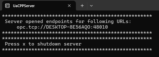
Figure 5-2 — UaCPPServer on the PC. The port at the end of that URL — 48010 — is what goes into the QEC’s target URL; the host part is the PC’s machine name, which is exactly what you must not type in (see §3.4). The machine name is masked in this figure.
6. Two QECs Paired: One Server, One Client
Flash one of each and leave the PC out of it. This is the fastest way to walk an OPC UA link end to end, and with a Log page on each side it is easy to tell which end a problem is on.
Because the two sketches ship on different subnets (§1), two things change on the client side — both on the panel, with no reflash:
| What to change | Change it to | When it takes effect |
|---|---|---|
IP / Gateway on the SETUP page | 192.168.2.201 / 192.168.2.1(same subnet as the server, and not a clashing IP) | After CONFIRM, two presses of REBOOT |
Target Server on the Home page | opc.tcp://192.168.2.200:4840 | After APPLY, on the next CONNECT |
Then check on the SETUP page that the Active now row now reads 192.168.2.201 — the left column is “stored in EEPROM”, the right one is “actually running”, and two that differ mean the device has not been restarted yet.
Press CONNECT on the client and browse to Objects ▸ QEC: the server’s ten nodes appear with live values, and at the same moment the server panel’s own LED lights and Sessions goes to 1 — you can watch both ends of the same connection at once.
QEC.Counter increments every second, which makes it the best node to try LIVE and WATCH on; Setpoint / Analog are read-only by design and are ready-made for confirming BadNotWritable.
The same reasoning applies to any existing server on site: the client’s IP has to land in the other end’s subnet, and the target URL takes the other end’s IP and port (
4840is the standard OPC UA port,48010belongs to Unified Automation’s demo server — do not mix them up).
7. Resources
- Server Development guides (PDF): QEC_OPCUA_Server_Guide_EN | QEC_OPCUA_Server_Guide_CN
- Client Development guides (PDF): QEC_OPCUA_Client_Guide_EN | QEC_OPCUA_Client_Guide_CN
- Example program (ZIP): QEC_OPCUA_Server | QEC_OPCUA_Client
- 86Duino IDE 502 and QEC software tools: Software
We will continue to deliver robust and innovative EtherCAT automation platforms for smarter, faster machine integration. For more info and sample requests, please write to info@icop.com.tw, call your nearest ICOP Branch, or contact our Worldwide Official Distributor.