[技術提示]
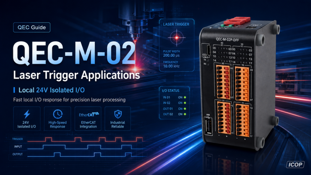
雷射加工設備——打標、切割、鑽孔、修整——通常要求「輸入到輸出」的觸發路徑在 100 µs內完成響應。我們實際接上一台 QEC-M-02 ,量測它的本地隔離 I/O 究竟能做到什麼程度。
結果如下:
QEC-M-02 本地 24 V 隔離 I/O,DO→DI 迴路(實測,約 25 °C,輕負載):上升緣(0→1):67.3 – 80.7 µs · 下降緣(1→0):90.9 – 94.2 µs。觀測到的時序離散範圍(最大−最小):13.4 µs(0→1)/3.3 µs(1→0)。
您可以在此下載報告: 202512_M02_DIO_0-1_Ans_v1r1.pdf
兩個邊緣皆實測低於 100 µs——所使用的不過是 86Duino Coding IDE 中一支簡單的 sketch,以及板載的隔離 I/O。不需要專用的觸發硬體,也不需要特殊韌體。
1. 這對雷射機台為何重要
雷射機台中典型的快速迴路: photoelectric sensor / encoder mark → DI → application logic → DO → laser gate or shutter driver。在 1 公尺/秒的平台速度下,每 100 微秒的延遲大約對應 100 µs 的行程——任何延遲變化都會造成無法透過校準消除的定位誤差。
使用遠端現場匯流排 I/O 時,此循環必須雙向運作在匯流排週期內。在傳統的循環配置(250 微秒 - 1 毫秒更新)中,完整的輸入-邏輯-輸出往返時間通常遠超 100 微秒的目標值——這並非協議限制,而是因為路徑需要兩次穿越總線。 EtherCAT 仍然是同步運動和分散式 I/O 的理想骨幹網路; QEC-M-02 的方法是將無法等待一個週期的循環保持在 本地:它的 16 個 DI / 16 個 DO 隔離通道由 Vortex86EX2 CPU 直接驅動,程式設計方式與此控制器上的其他所有部分相同- setup() 與 loop() 在 86Duino Coding IDE 中。
Sensor / Encoder Mark ──► Local DI (X00) ──► QEC-M-02 logic ──► Local DO (Y00) ──► Laser Gate

QEC-M-02 ──── EtherCAT ──── Servo Drives ──── Stage / Feeding Axis
一台控制器,兩種角色——不需要獨立的高速觸發盒。(本文的量測是針對本地 I/O 路徑本身的特性;若要在您自己的應用工作負載下驗證時序,請見第 3 節。)
2. 我們如何量測
我們在 24 V 現場側,將本地 DO(Y00)迴接到本地 DI(X00),如此一次量測即涵蓋完整路徑:DO 切換 + 接線 + DI 門檻跨越 + 軟體偵測。時序採用 CPU 時間戳計數器(在 533 MHz 下 1 tick ≈ 1.875 ns),並以 Tektronix TDS2012C 示波器交叉驗證。
簡化的時序迴路片段(僅供基準測試使用——正式版本應加入逾時機制,並在每一條離開路徑上都恢復中斷):
io_DisableINT();                       // suppress software jitter
uint64_t t0 = timer_GetClocks64();
writeDO(Y00, HIGH);                    // 0 -> 1 rising edge
while (readDI(X00) == 0);              // busy-wait for loopback
uint64_t t1 = timer_GetClocks64();
io_EnableINT();

double delay_us = (double)(t1 - t0) / 533.0;
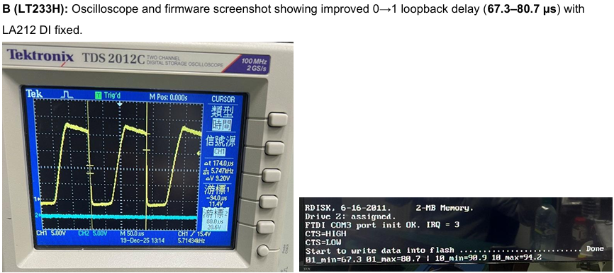
| Transition | Minimum | Maximum | Observed spread |
|---|---|---|---|
| 0→1 (rising) | 67.3 µs | 80.7 µs | 13.4 µs |
| 1→0 (falling) | 90.9 µs | 94.2 µs | 3.3 µs |
2.1 關於規格書上的數字
QEC-M-02 規格書標示數位輸出的導通 (turn-on)為 0.25 ms/關斷(turn-off)為 20 µs,額定條件為滿載 500 mA。上述量測是在輕負載下進行——DO 僅驅動 DI 輸入,數十 mA 而已,這也是驅動雷射控制器邏輯準位閘極(gate)輸入時的典型情況。PhotoMOS 輸出級在輕負載下導通會快得多(而關斷則略慢),量測結果正是如此。兩組數字在各自的條件下都是正確的: 規格書仍是保證規格;而本文中的數值是在所述測試條件下的實測行為。 若您的設計中響應時間至關重要,請讓 DO 負載保持輕量——並以緩衝方式處理重負載,而非直接驅動。
3. 在您自己的工作台上試試
這項測試刻意設計得容易重現:在 24 V 端子台上用一條跳線把 Y00 接到 X00,再加上前述在 86Duino Coding IDE 中的時序迴路即可。我們的基準測試單獨執行時序迴路以建立乾淨的基線;同一支 sketch 可原封不動地與您的 EtherCAT 網路及應用邏輯並行執行,因此您可以在真實工作負載下量測其分佈——那才是對您的機台真正重要的數字。完整的測試 sketch 可向我們的團隊索取。
請注意,這裡的數字是控制器在整個迴路中所佔的部分;您的系統總量還要加上感測器的響應時間,以及雷射控制器的輸入級。另外提醒一項安全事項:標準數位輸出僅用於 製程觸發 ——雷射安全連鎖(interlock)、緊急停止,以及其他安全等級的功能,應交由通過認證的安全裝置,而非一般用途 I/O 來負責。
想確認它是否符合您的製程?
聯繫我們 info@icop.com.tw 索取測試 sketch 或評估樣機 ——我們的 FAE 經常為雷射應用審視「感測器 → DI」與「DO → 雷射閘極」的接線。
我們將持續提供穩健且創新的 EtherCAT 自動化平台,實現更智慧、更快速的整合。如有任何問題或需要支援,請透過 info@icop.com.tw、您當地的 ICOP分公司或 全球官方經銷商.