このライブラリを使用すると、86Duino をマスターデバイスとして SPI デバイスと通信できます。
このライブラリを使用するには#include <SPI.h>
シリアルペリフェラルインターフェース(SPI)の簡単な紹介
シリアル・ペリフェラル・インターフェース(SPI)は、マイクロコントローラが1つまたは複数の周辺機器と短距離で高速通信するために使用する同期シリアルデータプロトコルです。また、2つのマイクロコントローラ間の通信にも使用できます。
SPI接続では、周辺機器を制御するマスターデバイス(通常はマイクロコントローラ)が常に1つ存在します。通常、すべてのデバイスに共通する3本の線があります。
- MISO (Master In Slave Out) – マスターにデータを送信するためのスレーブライン
- MOSI (Master Out Slave In) – 周辺機器にデータを送信するためのマスターライン
- SCK (Serial Clock) - マスターによって生成されたデータ転送を同期させるクロックパルス
各デバイスごとに固有の 1 行があります。
- SS (Slave Select) – マスターが特定のデバイスを有効または無効にするために使用できる各デバイスのピン。
デバイスのスレーブセレクトピンがローレベルのとき、デバイスはマスターと通信します。ハイレベルのとき、デバイスはマスターを無視します。これにより、複数のSPIデバイスで同じMISO、MOSI、SCKラインを共有できます。
新しい SPI デバイスのコードを書くには、いくつか注意すべき点があります。
- データは最上位ビット (MSB) からシフトされますか、それとも最下位ビット (LSB) からシフトされますか?
これは、SPI.setBitOrder()関数によって制御されます。 - データクロックはハイまたはローのときにアイドル状態になりますか?
サンプルはクロックパルスの立ち上がりエッジまたは立ち下がりエッジにありますか?これらのモードは、SPI.setDataMode()関数によって制御されます。 - SPI はどのくらいの速度で動作していますか?
これは、SPI.setClockDivider()関数によって制御されます。
SPI規格は緩く、デバイスごとに実装が異なります。そのため、コードを書く際にはデバイスのデータシートを特に注意深く確認する必要があります。
一般的に、伝送には4つのモードがあります。これらのモードは、データクロック信号の立ち上がりエッジと立ち下がりエッジのどちらでデータがシフトインおよびシフトアウトされるか(クロック位相と呼ばれます)と、クロックがハイまたはローのどちらでアイドル状態になるか(クロック極性と呼ばれます)を制御します。4つのモードは、極性と位相を次の表に従って組み合わせます。
| Mode | Clock Polarity (CPOL) | Clock Phase (CPHA) |
SPI_MODE0 | 0 | 0 |
SPI_MODE1 | 0 | 1 |
SPI_MODE2 | 1 | 0 |
SPI_MODE3 | 1 | 1 |
SPI.setDataMode() 関数を使用すると、クロックの極性と位相を制御するモードを設定できます。
すべてのSPIデバイスには、SPIバスの最大許容速度があります。SPI.setClockDivider() を使用すると、デバイスが正常に動作するようにクロック速度を変更できます。
SPIパラメータを正しく設定したら、デバイスのどのレジスタがどの機能を制御しているかを把握するだけで準備完了です。これはデバイスのデータシートに記載されています。
SPI の詳細については、Wikipedia の SPI に関するページを参照してください。
接続
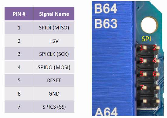
次の表は、さまざまな 86Duino ボードで SPI ラインがどのピンに分割されているかを示しています。
| 86Duino Board | MOSI | MISO | SCK | SS |
| Zero | SPIDO | SPIDI | SPICLK | SPICS |
| One | SPIDO | SPIDI | SPICLK | SPICS |
| Educake | – | – | – | – |
MISO、MOSI、SCK、および SS は、SPI ヘッダー上の一貫した物理的な場所で使用できることに注意してください。これは、たとえば、すべてのボードで動作するシールドを設計する場合に便利です。
機能
- begin()
- end()
- setBitOrder()
- setClockDivider()
- setDataMode()
- setSS()
- transfer()
事例
以下は、Arduino Tutorial の SPI ライブラリの例で、86Duino ボードで使用できます (ただし、これらの例の回路を参照する場合、86Duino の SPI ピンの位置は、これらの例で採用されている Arduino ボードの位置と異なることに注意してください)。
- BarometricPressureSensor: SPIを使用してセンサーから気圧と温度を読み取る
- SPIDigitalPot: SPIを使ってデジタルポテンショメータを制御する
参照
ライブラリリファレンスホーム
86Duinoリファレンスのテキストは、Arduinoリファレンスを改変したもので、Creative Commons Attribution-ShareAlike 3.0ライセンスに基づいてライセンスされています。リファレンス内のコードサンプルはパブリックドメインとして公開されています。